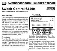
Untitled - Uhlenbrock
Untitled - Uhlenbrock
Untitled - Uhlenbrock

You also want an ePaper? Increase the reach of your titles
YUMPU automatically turns print PDFs into web optimized ePapers that Google loves.
MARCoStation control with passing loop is possible in these operating modes as already described.The following LNCVs must be programmed:LNCV Description Value13 0= No coupling of Exit Manager and Entry Manager 0120 Address with which the Entry Manager reports the passing loop as 1-4095occupied.The addresse (LNCV 0) must not be used by any other MARCo-Receiver.121 Route from the station entrance to the station exit10-20483Instruction for switching route in the Intellibox, Intellibox II or IB-Switch,that leads from the staition entrance (Block with the Entry Manager) tothe Exit Manager (Block with the Exit Manager).122 If a train arrives at in the passing loop the instruction entered here is10-20483executed.123 If a train arrives at in the passing loop the instruction entered here isexecuted.10-204837.4.6 Extended Functions for Shuttle service, Holding Point and Block SectionThe automatic functions, Shuttle train time controlled, Shuttle train remote controlled, holdingpoint and block section can be combined with three additional functions which are described inthe following section.Overall Switching OperationOnce the basics are working, the time delays for shuttle train may need to be modified.Chapter 7.3.6 shows how to switch solenoids for signals or routes and/or sending feedback.With LNCV 7 and LNCV 8 there are two ways to produce such instructions. Theseinstructions are implemented immediately after the detectors are passed, independent of therecognized vehicle address, i.e. all vehicles switch the same solenoids and/or routes and sendthe same feedback.LNCV Description7 1.Solenoid, Feedback or RouteAddress and direction of a second solenoid to be switched, i.e. the address has 0 or 1 added,and/or address of a route or address of a feedback with attachedStatus 3 for “occupied” or 2 for “vacant” or the address of a routeNote: The signal does not have to physically be on the layout.8 2. Solenoid, Route or feedbackAddress and direction of a second solenoid to be switched, i.e. the address has 0 or 1 added,and/or address of a route or address of a feedback with attachedStatus 3 for “occupied” or 2 for “vacant” or the address of a route.Note: The signal does not have to physically be on the layout.Individual Switching OperationChapter 7.3 is concerned with switching operations, how set up a specific vehicle’s functions,speeds or solenoid change and/or sending Feedback. All switching functions described canalso be programmed individually for automated shuttle train systems.Chapter 7.3 described adjusting command options, whether the programmed Instruction isexecuted the instant the detectors are passed or later when the automatic departure is to beimplemented. Speed instructions generally are implemented only at departure.65