Untitled - Uhlenbrock
Untitled - Uhlenbrock
Untitled - Uhlenbrock

You also want an ePaper? Increase the reach of your titles
YUMPU automatically turns print PDFs into web optimized ePapers that Google loves.
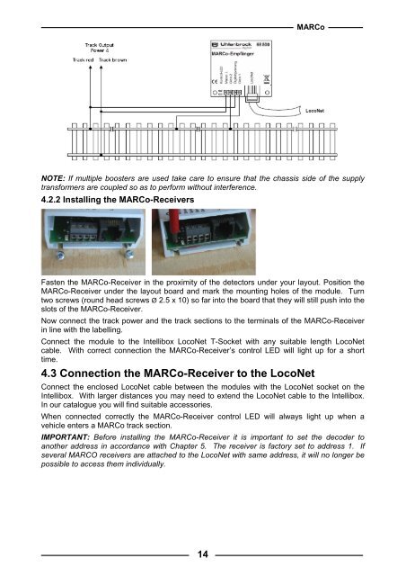
MARCoNOTE: If multiple boosters are used take care to ensure that the chassis side of the supplytransformers are coupled so as to perform without interference.4.2.2 Installing the MARCo-ReceiversFasten the MARCo-Receiver in the proximity of the detectors under your layout. Position theMARCo-Receiver under the layout board and mark the mounting holes of the module. Turntwo screws (round head screws Ø 2.5 x 10) so far into the board that they will still push into theslots of the MARCo-Receiver.Now connect the track power and the track sections to the terminals of the MARCo-Receiverin line with the labelling.Connect the module to the Intellibox LocoNet T-Socket with any suitable length LocoNetcable. With correct connection the MARCo-Receiver’s control LED will light up for a shorttime.4.3 Connection the MARCo-Receiver to the LocoNetConnect the enclosed LocoNet cable between the modules with the LocoNet socket on theIntellibox. With larger distances you may need to extend the LocoNet cable to the Intellibox.In our catalogue you will find suitable accessories.When connected correctly the MARCo-Receiver control LED will always light up when avehicle enters a MARCo track section.IMPORTANT: Before installing the MARCo-Receiver it is important to set the decoder toanother address in accordance with Chapter 5. The receiver is factory set to address 1. Ifseveral MARCO receivers are attached to the LocoNet with same address, it will no longer bepossible to access them individually.14