- Page 1 and 2: Characterization ofClocks and Oscil
- Page 3 and 4: PREFACEFor many years following its
- Page 5 and 6: 0 • • • • • • • •
- Page 7 and 8: 0 •• 0 •• 0 •• 0 •
- Page 9 and 10: TOPICAL INDEX TO ALL PAPERSThe foll
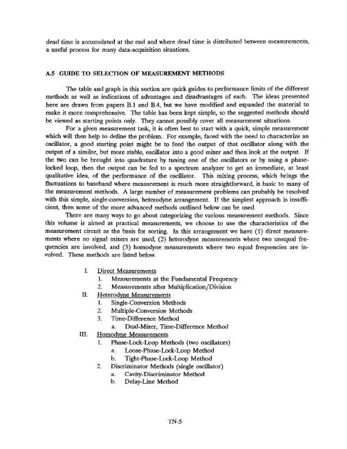
- Page 11 and 12: of the wide range of measurement si
- Page 13: The first of these (D.l) by Lesage
- Page 17 and 18: 10- 1410- 15c-een10- 1610- 1710- 18
- Page 19 and 20: Table 2. Ratio of mod a~('r) to a~(
- Page 21 and 22: of the frequency measured in this m
- Page 23 and 24: From: Proceedings of the 35th Annua
- Page 25 and 26: where V0 ;: nomi na I peak vo Itage
- Page 27 and 28: ports of the pair of double balance
- Page 29 and 30: fluctuations prior to the bias box
- Page 31 and 32: up an interesting hierarchy of kind
- Page 33 and 34: is determi ned by the measurement s
- Page 35 and 36: Since each average of the fractiona
- Page 37 and 38: Thus. with 9~ probability the calcu
- Page 39 and 40: in fact. Also for n=l the "experime
- Page 41 and 42: 1n tenns of the typical performance
- Page 43 and 44: and eq (1.1) we get2m>(t) = ~T(t) =
- Page 45 and 46: varactor control in th@ reference o
- Page 47: V nn5(45 Hz) = 100 nV por root hort
- Page 50 and 51: We can use the convolution theorem
- Page 52 and 53: though the concept of harmonics in
- Page 54 and 55: and wz(t) is now the si!npled versi
- Page 56 and 57: 10.7 Time Domain-Frequency Domain T
- Page 58 and 59: o/(t). In the table, the left colum
- Page 60 and 61: Weean make the following general re
- Page 62 and 63: -flO• r.1OSP1 t(f2-,~ 1Ci~-/'10 f
- Page 64 and 65:
frequency extent of the analysis ba
- Page 66 and 67:
28. P. Kartaschoff and J. Barnes, "
- Page 68 and 69:
_--_._~--~II..gIIIIII1.......oIIIII
- Page 70 and 71:
From: Precision FrequenC)' Control,
- Page 72 and 73:
12 FREQUENCY AND TIME MEASUREMENT 1
- Page 74 and 75:
12 FREQUENCY AND TIME MEASUREMENT19
- Page 76 and 77:
12 FREQUENCY AND TIME MEASUREMENT19
- Page 78 and 79:
12 FREQUENCY AND TIME MEASUREMENT19
- Page 80 and 81:
12 FREQUENCY AND TIME MEASUREMENT 2
- Page 82 and 83:
12 FREOU::NCY AND TIME MEASUREMENT2
- Page 84 and 85:
12 FREQUENCY AND TIME MEASUREMENT20
- Page 86 and 87:
12 FREQUENCY AND TIME MEASUREMENT20
- Page 88 and 89:
12 FREQUENCY AND TIME MEASUREMENT20
- Page 90 and 91:
12 FREQUENCY AND TIME MEASUREMENTI~
- Page 92 and 93:
12 FREQUENCY AND TIME MEASUREMENT21
- Page 94 and 95:
12 FREOUENCV AND TIME MEASUREMENT21
- Page 96:
12 FREQUENCY AND TIME MEASUREMENT21
- Page 100 and 101:
12 FREQUENCY AND TIME MEASUREMENT22
- Page 102 and 103:
12 FREQUENCY AND TIME MEASUREMENT22
- Page 104 and 105:
12 FREQUENCY AND TIME MEASUREMENT22
- Page 107 and 108:
228 SAMUEL R. STEIN9.3 GHzOSCILLATO
- Page 109 and 110:
230 SAMUEL R. STEINThe combination
- Page 111 and 112:
232 SAMUEl R STEINHowever, the spec
- Page 113 and 114:
400 CHAPTER BIBLIOGRAPHIESAllan. D.
- Page 115 and 116:
402 CHAPTER BIBLIOGRAPHIESBaugh. R.
- Page 117 and 118:
404 CHAPTER BIBLIOGRAPHIESConway. A
- Page 119 and 120:
406 CHAPTER BIBLIOGRAPHIESGardner.
- Page 121 and 122:
408 CHAPTER BIBLIOGRAPHIESJackisch.
- Page 123 and 124:
410 CHAPTER BIBLIOGRAPHIESlesage. P
- Page 125 and 126:
412 CHAPTER BIBLIOGRAPHIESPaul. F.
- Page 127 and 128:
414 CHAPTER BIBLIOGRAPHIESSorden. J
- Page 129 and 130:
416 CHAPTER BIBLIOGRAPHIESYoshimura
- Page 131 and 132:
648IEEE TRANSACTIONS ON ULTRASONICS
- Page 133 and 134:
650 IEEE TRANSACTIONS ON ULTRASONIC
- Page 135 and 136:
652 IEEE TRANSACTIONS ON ULTRASONIC
- Page 137 and 138:
IEEE TRANSACTIONS ON ULTRASONICS. F
- Page 139 and 140:
Powet spectral analysis of the outp
- Page 141 and 142:
major difficulty is designing a mix
- Page 143 and 144:
The phase noise in the source can c
- Page 145 and 146:
detail elsewhere [12]. The low pass
- Page 147 and 148:
NJ:",--0~.8~..(/)-110-1:20-130-140m
- Page 149 and 150:
is ~he preferred measure, since, un
- Page 151 and 152:
2. Copy.r,ion Beeween Frequency and
- Page 153 and 154:
All.n, D. Y., .nd D...s, H., Picose
- Page 155 and 156:
105Characterization of Frequency St
- Page 157 and 158:
B'R:sES et ai.: ClHR.,CTY.RIZHIO:-r
- Page 159 and 160:
e4.RNES et al.: CH."R.ACTERrZ.4.TIO
- Page 161 and 162:
MII.NES et al.. CHAIl.ACfERlZATlO:-
- Page 163 and 164:
:l frequcllcy ~eparatioll froll1 th
- Page 165 and 166:
MRNES et al.: CHARACTERIZATION OF F
- Page 167 and 168:
B\R~f:S eL al.: CIHRACTERIZ.,TIOI<
- Page 169 and 170:
8IR:-IES et al.: CH.'R.'CTER[Z.
- Page 171 and 172:
142 Rep. 580--2Reprinted, with perm
- Page 173 and 174:
i44 Rep. 580-2If the initial sampli
- Page 175 and 176:
146 Rep. 580-2The values of ha are
- Page 177 and 178:
148 Rep. SSO-2TABLE II - Translalio
- Page 179 and 180:
ISO Rep. 580-2, 738-2BIBLIOGRAPHYAL
- Page 181 and 182:
522 LESAGE AND AUDOIN01., 1971J:S,I
- Page 183 and 184:
524 LESAGE AND AUDOINKl- 1410- 11 \
- Page 185 and 186:
526LESAGE AND AUDOINQuartz ClJstalF
- Page 187 and 188:
528 LESAGE AND AUDOINMinrFrequent,r
- Page 189 and 190:
530 LESAGE AND AUOOINsuch as c:r;(T
- Page 191 and 192:
532 LESAGE AND AUDOINl.l-TEquations
- Page 193 and 194:
534 LESAGE AND AUDOINof measurement
- Page 195 and 196:
LESAGE AND AUDOIN2 - Vo )]53610- 1
- Page 197 and 198:
538 LESAGE AND AUWINstability measu
- Page 199 and 200:
Copyright Ie) 1984 Academic Press.
- Page 201 and 202:
7. PHASE NOISE AND AM NOISE MEASURE
- Page 203 and 204:
7. PHASE NOISE AND AM NOISE MEASURE
- Page 205 and 206:
7. PHASE NOISE AND AM NOISE MEASURE
- Page 207 and 208:
7. PHASE ~OISE AND AM NOISE MEASURE
- Page 209 and 210:
7. PHASE NOISE AND AM NOISE MEASURE
- Page 211 and 212:
7. PHASE :'-iOrSE AND AM NOISE MEAS
- Page 213 and 214:
or, in rms radians,7. PHASE !'rOISE
- Page 215 and 216:
i. PHASE :-JOISE AND AM NOISE MEASU
- Page 217 and 218:
7. PHASE NOISE AND AM NOISE MEASURE
- Page 219 and 220:
7. PHASE NOISE AND AM NOISE MEASURE
- Page 221 and 222:
7. PHASE ~OISE AND AM NOISE MEASVRE
- Page 223 and 224:
7. PHASE NOISE AND AM NOISE MEASURE
- Page 225 and 226:
7. PHASE NOISE AND AM NOISE MEASURE
- Page 227 and 228:
7. PHASE NOISE AND AM NOISE MEASURE
- Page 229 and 230:
7. PHASE NOISE AND AM NOISE MEASURE
- Page 231 and 232:
7. PHASE NOISE AND AM NOISE MEASURE
- Page 233 and 234:
7. PHASE NOISE AND AM NOISE MEASURE
- Page 235 and 236:
7. PHASE NOISE AND AM NOISE MEASURE
- Page 237 and 238:
7. PHASE NOISE AND AM NOISE MEASURE
- Page 239 and 240:
7. PHASE NOISE AND AM NOISE MEASURE
- Page 241 and 242:
7. PHASE NOISE AND AM NOISE MEASURE
- Page 243 and 244:
7. PHASE NOISE AND AM :>lOISE MEASU
- Page 245 and 246:
_~ ~A _7. PHASE NOISE AND AM NOISE
- Page 247 and 248:
7. PHASE NOISE AND AM NOISE MEASURE
- Page 249 and 250:
7. PHASE NOISE AND AM NOISE MEASURE
- Page 251 and 252:
average frequency over the interval
- Page 253 and 254:
and frequency stability of precisio
- Page 255 and 256:
PHASE P~OT Clook No. ~- e I"d,....
- Page 257 and 258:
BL-\5ES .-\.\D \·A.Rl.-\.\CES OF S
- Page 259 and 260:
to a g
- Page 261 and 262:
while the Hanning ""!Odo"" yIelds1.
- Page 263 and 264:
Proc. 35th Ann. Freq. Control Sympo
- Page 265 and 266:
N-3n+lEj=1Mod Oy2 (t) =0 2(t) {.! +
- Page 267 and 268:
(a)1SIMULATED NOISE(b)1-10- 2- --10
- Page 269 and 270:
IEEE TRANSACTIONS ON INSTRUMENTATlO
- Page 271 and 272:
IEEE TRANSACTIONS ON INSTRUYlENTATI
- Page 273 and 274:
From: Proceedings of the 15th Annua
- Page 275 and 276:
where c = Dr/2. In regression analy
- Page 277 and 278:
'" Dr 22 = -7.507E-16 (about -6.5E-
- Page 279 and 280:
Coefficient of simple determination
- Page 281 and 282:
100%CUMULATIVE PERIODOGRAM ~50%(,
- Page 283 and 284:
100%CUMULATIVE PER I ODOGRAM50%U'10
- Page 285 and 286:
TABLE 6.STANDARD DEVIATIONSPROCEDUR
- Page 287 and 288:
APPENDIX AREGRESSION ANALYSIS(Equal
- Page 289 and 290:
andG == N (N - 1) (N - 2)Also, the
- Page 291 and 292:
APPENDIX BREGRESSIONS ON LINEAR AND
- Page 293 and 294:
REFERENCES1. D.W. Allan, "The Measu
- Page 295 and 296:
5.12 )( 10 - 7 SEC
- Page 297 and 298:
100%CUMULATIVE PERIODOGRAM -50%U'
- Page 299 and 300:
100%CUMULATIVE PERIODOGRAM50%(J'l..
- Page 301 and 302:
FREQUENCY DRIFT AND WHITESTANDARD D
- Page 303 and 304:
MR. McCASKILL:Well, let me go furth
- Page 305 and 306:
NIST Technical Note 1318, 1990.VARI
- Page 307 and 308:
By definition, white noise has a po
- Page 309 and 310:
where aZ(N,T,r) is the expected sam
- Page 311 and 312:
Some useful asymptotic forms of B 3
- Page 313 and 314:
Since the time-domain definition fo
- Page 315 and 316:
Stability Using Non-zero Dead-Time
- Page 317 and 318:
I!II.....I~I.....cIQ)IEQ) I~I~(J)
- Page 319 and 320:
-2,THE BIAS FUNCTION, 8 2 (r,p.)Fig
- Page 321 and 322:
AppendixWith reference to figure 1,
- Page 323 and 324:
8lIN,r,lll) for r = .011\1\ N= ~ 81
- Page 325 and 326:
BUN,r,IItJI for r =/tl\ !'I= 8 16 3
- Page 327 and 328:
81 (N,r,lIUl for r =ItJ \ IF 4 8 16
- Page 329 and 330:
__ ....... ~...........__ .........
- Page 331 and 332:
BllN,r,kl) for r = 1024It! \ N= 4 B
- Page 333 and 334:
B2(r,llU)It! \ r = .0001 .0003 .001
- Page 335 and 336:
B3( 2, P1,I", IIU) far r '" .01~\ ~
- Page 337 and 338:
83(2,I'f,r,~)for r '"""'III \ 2 4 B
- Page 339 and 340:
B312.I'I,r,llU) for r " 4I\J \ pt::
- Page 341 and 342:
B3(2,I'I,r,lIJ) Fer r ~ MI\J\ PI::
- Page 343 and 344:
B3(2,"',r,ail for r = 1024MIl \ I'l
- Page 345 and 346:
E. APPENDIX - Notes and ErrataThe n
- Page 347 and 348:
Influence of Pressure and Humidity
- Page 349 and 350:
22. page TN-160In eqs (101), (102),
- Page 351 and 352:
29. page TN-180If the ratio of T/ T
- Page 354:
NIST-114A(REV. 3-89)4. TITLE AND SU