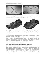
NIST Technical Note 1337: Characterization of Clocks and Oscillators
NIST Technical Note 1337: Characterization of Clocks and Oscillators
NIST Technical Note 1337: Characterization of Clocks and Oscillators

Create successful ePaper yourself
Turn your PDF publications into a flip-book with our unique Google optimized e-Paper software.
(5) All oscillators in the range <strong>of</strong> 5 MHz ± 5H~ may be compared. Other carrier frequenCles such as 1 MHz, 5.115 MHz, 10 MHz <strong>and</strong>10.23 101Hz are also usable. However, differentcarrier frequencies may not be mixedon the same system. The sys tem has beensuccessfully tested with an oscillator <strong>of</strong>fset4.6 Hz from nominal 5MHz. Measurementswere made at intervals <strong>of</strong> 2 hours betweenwhich the sys~m had to accumulate approximately2 x 10 n. The system has also b~§ntested with an oscillator <strong>of</strong>fset 4 x 10 ,<strong>and</strong> no errors were detected during a period<strong>of</strong> 40 days.(6) All sampling times in the range <strong>of</strong> 1 secondto 16 days with a resolution <strong>of</strong> 0.1 secondare possible. Measurements may be made oncomm<strong>and</strong> or in a preprogrammed sequence.(7) Measurements are synchronized precisely,i.e. at the picosecond level, with thereference clock. They may therefore besynchronized with important user systemevents, such as the switching times <strong>of</strong> aFSK or PSK system.(B)All oscillators are compared synchronously<strong>and</strong> all measurements are performed within amaximum interval <strong>of</strong> 0.1 second. As a result,the phase <strong>of</strong> any oscillator needs tobe i nterpo1ated to the chosen measurementtime for an interval <strong>of</strong> 0.1 second maximum.This capability, which is not present ineither si ngl e heterodyne measurement systemsor switched measurement systemseliminates a source <strong>of</strong> "measurement" errorwhich is generally much larger than thenoise induced errors. For example, interpe1ation<strong>of</strong> the PD!!e Rf a high performanceCs clock (0 - 10 II~) over a period <strong>of</strong> 3hours would' produce approximately 1.5 nsphase uncertainty. To maintain 4 ps accuracyrequ i res measurements simultaneous toO.ls.(9) There are no phase errors due to the switching<strong>of</strong> rf signals since there is noswitching anywhere in the analog measurementsystem.(10) No appreciable phase errors are introducedwhen it is necessary to change the referenceclock since, as shown in Figure 6, thepeak error due to changes in synthesizerphase is 20 ps.(11) The measurement system is capable <strong>of</strong> measuringits own phase noise when the samesignal is app1 ied to two input ports.Figure 7 shews the phase deviations betweentwo such channels over a period <strong>of</strong> 75,000seconds <strong>and</strong> Fi gure B is the correspondi ngAllan variance plot. ~igure 9 shows thephase deviations between 2 input channelsover a period <strong>of</strong> 40 days.(12) Since the IEEE-533 (CAMAC) interface st<strong>and</strong>ardhas been followed for all tne customhardware, the system may be easily interfacedto almost any instrument controller.NBS has already tes ted the sys tern us i ng alarge minicomputer, a small minicomputer<strong>and</strong> a desk top calculator. Interfacesbetween IEEE-583 <strong>and</strong> IEEE-48B controllersare available <strong>and</strong> have been used successfully.(13) The system is capable <strong>of</strong> camparing a verylarge number <strong>of</strong> oscillators at a reasonablecost per device.There are also disadvantages to this measurementsystem. The most important are:(l) The camp 1exity <strong>of</strong> the hardware is greaterthan for some systems. It is possiblethat this will reduce reliability.(2) A high level <strong>of</strong> redundancy is difficult toachieve. The system design stresses size,power, convenience <strong>and</strong> cost, resulting inan increase in the number <strong>of</strong> possiblesingle point failure mechanisms compared tosome other techniques. For example, aCAMAC power supply failure will result in aloss <strong>of</strong> data for all devices being measured.(3) A SUbstantial committment is required inboth specialized hardware <strong>and</strong> s<strong>of</strong>tware.(4) If an oscillator under test experiences aphase jump which exceeds 1 cycle, themeasurement system records a jump withincorrect absolute magnitude. As a reSUlt,it may not be applicable to signals whichare frequency modulated with discontinuousphase steps larger than 2n.ConclusionsWe have demonstrated a new phase measurementsystem with very desirable properties: Alloscll 1ators in the range <strong>of</strong> 5MHI ± 5Hz may bemeasured directly. The sampling times are onlyrestricted by the requirement that they exceedone jiecond. The noise floor is a (2,t) = 3 x10- 1 It in short term <strong>and</strong> the tin?e deviationsare less than 100 ps. All circuitry is designedas modules which allows expansion at modestcost. Compatibility with a variety <strong>of</strong> computersis insured through the use <strong>of</strong> the lEEE-5B3interface <strong>and</strong> adapters are available to permituse with an IEEE-4BB controller. The systemmakes it feasible to make completely automatedphase measurements at predetermined times onlarge numbers <strong>of</strong> atomic clocks. It's own noiseis one-hundred times less than the state-<strong>of</strong>-theartin clock performance. It will be used inthe near future to make all measurement neededto compute NBS atomic time, but it will also bevery valuable for any laboratory which usesthree or more atomic clocks.References1. O. W. Allan, "The measurement <strong>of</strong> frequency316