NIST Technical Note 1337: Characterization of Clocks and Oscillators
NIST Technical Note 1337: Characterization of Clocks and Oscillators
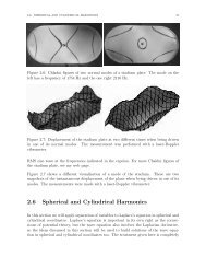
NIST Technical Note 1337: Characterization of Clocks and Oscillators

Create successful ePaper yourself
Turn your PDF publications into a flip-book with our unique Google optimized e-Paper software.
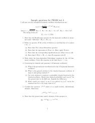
given byREFV",(f) ]2(10)[G(f)~ P,IJMeasurement <strong>of</strong> Scp(f) lor Two AmplifiersS~lf). (-- V. )' ~ G(')K. BW(<strong>of</strong>ten more than 20 dB). Termination <strong>of</strong> the mixer IFport with 50 n maximizes the IF b<strong>and</strong>width, however,termination with reactive loads can reduce the mixernoise by - 6 dB, <strong>and</strong> increase K dby 3 to 6 dB asshown in Fig. 3 [4J. Accurate determination <strong>of</strong> K dcan be achieved by measuring the slope <strong>of</strong> the zerocrossing in volts/radian with an oscilloscope orother recording device when the two oscillators arebeating slowly. For some applications the digitizerin the spectrum analyzer can be used to measure boththe beat period <strong>and</strong> the slope in Vis at the zerocrossing. The time axis is easily calibrated sinceone beat period equals 2~ radians. The slope involts/radian is then calculated with a typicalaccuracy <strong>of</strong> 0.2 dB. Estimates <strong>of</strong> K dobtained frommeasurements <strong>of</strong> the peak to peak output voltageinduced can introduce errors as large as 6 dB inS~(f) even if the amplitude <strong>of</strong> the other harmonics ismeasured unless the phase relationship 1s also takeninto account [4]. S~(f) can be made independent <strong>of</strong>the accuracy <strong>of</strong> the spectrum analyzer voltagereference by comparing the level <strong>of</strong> an externally IFsignal (a pure tone is best), on the spectrumanalyzer used to measure V nwith the level recordedon the device used to measure K d.Fig. 2. Precision phase measurement system featuringself calibration to 0.4 dB accuracy from dc to 0.1 vaFourier frequency <strong>of</strong>fset from carrier. This systemis suitable for measuring signal h<strong>and</strong>ling equipment,multipliers, dividers, frequency synthesizers, aswell as passive components [4J.S0.8r--,.--,--r--r--,O.OlIJF~ 0.7 2mW MIXER DRIVE~>!::0.6> 0.5i=fi)Z 0.4w«)0.3WIJJi4:J:a-0.210mW MIXER DRIVE0.11 2 5 10 202 51020 50 100FREQUENCY (kHz)Fig. 3. Double-balanced mixer phase sensitivity at 5KHz as a function <strong>of</strong> Fourier frequency for variousoutput terminations. The curves on the left wereobtained with 10 mlJ drive while those on the rightwere obtained with 2 mlol drive. The data demonstratea clear choice between constant, but low sensitivityor much higher, but frequency dependent sensitivity[4J.where V",(f) is the RKS noise voltage at Fourierfrequency f from the carrier measured after IF gainG(f) in a noise b<strong>and</strong>width RIJ. Obviously RIJ must besmall compared to f. This is very important whereS~(f) is changing rapidly with f, e.g., S~(f) <strong>of</strong>tenvaries as f- 3 near the carrier. In Fig. 1, theoutput <strong>of</strong> the second amplifiQr foLlovins the mixercontains contributions from the phase noise <strong>of</strong> theoscillators, the noise <strong>of</strong> the mixers, <strong>and</strong> the postamplifiers for Fourier frequencies much larger thanthe phase-lock loop b<strong>and</strong>width. In Fig. 2, the phasenoise <strong>of</strong> the oscillator cancQls out to a high degreelkQThe noise b<strong>and</strong>width <strong>of</strong> the spectrum analyzer alsoneeds to be verified. This calibration procedure issufficient for small Fourier frequencies but loosesprecision <strong>and</strong> accuracy due to the problemsillustrated in Fig. 3 <strong>and</strong> the variations <strong>of</strong> amplifiergain with Fourier frequency. If measurements need tobe made at Fourier frequencies near or below thephase-lock-loop b<strong>and</strong>width, a probe signal can beinjected inside the phase-lock-loop <strong>and</strong> theattenuation measured versus Fourier frequency.Some care is necessary to assure that the spectrumanalyzer is not saturated by spurious signals such asthe power line frequency <strong>and</strong> its multiples.Sometimes aliasing in the spectrum analyzer is aproblem. If narrow spectral features are to bemeasured it is usually recommended that a flat topwindow function (in the spectrum analyzer) be used.In the region where the measured noise is changingrapidly with Fourier frequency, the noise b<strong>and</strong>widthshould be much smaller than the measurementfrequency. The approximate level <strong>of</strong> the noise floor<strong>of</strong> the measurement system should be measured in orderto verify that it does not significantly bias themeasurements or, if necessary, to subtract its effectfrom the results.Typical best performance for various measurementtechniques is shown in Fig. 4. The two oscillatorapproach exceeds the performance <strong>of</strong> almost allavailable oscillators from below 0.1 MHz to over 100GHz <strong>and</strong> is generally the technique <strong>of</strong> first choicebecause <strong>of</strong> its versatility <strong>and</strong> simplicity. Figs. 10- 12 give some examples. Phaae noise measurements onpairs <strong>of</strong> signal sources can be made with an absoluteaccuracy better than 1 d! using the above calibrationprocedure. Such accuracy is not always attainablewhen the phase noise <strong>of</strong> the source exceeds that <strong>of</strong>the added noise <strong>of</strong> the components under test (seeFig. 2). The use <strong>of</strong> specialized high level mixerswith multiple diodes per leg increases the phase tovoltage conversion sensitivity, K d <strong>and</strong> thereforereduces the contribution <strong>of</strong> IF amplifier noise 15] asshown in Fig. 4. Phase noise measurements Cangenerally be made at Fourier frequencies fromapproximately de to 1/2 the source frequency. The434