


Create successful ePaper yourself
Turn your PDF publications into a flip-book with our unique Google optimized e-Paper software.
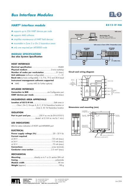
Bus Interface ModulesHART ® interface module8512-IF-HA◆ supports up to 256 HART devices per node◆ supports AMS software◆ simplifies maintenance of HART field devicesRS232/RS485ConverterWorkstation PCRunning “AMS” software(Asset Management Solutions)Safe area◆ mountable in Zone 2 or Div 2 hazardous areas◆ only one required per MTL<strong>8000</strong> nodeMTL<strong>8000</strong>node 1Safe area or Zone 2/Div 2 hazardous areaMTL<strong>8000</strong>node 2MODULE SPECIFICATIONSee also System Specification8512 8512HOST INTERFACEElectrical specification ................................................RS485Physical medium...........................................2-wire multidropNumber of nodes per workstation ......................31 (max.)Unit addresses (software configurable) ..........................1 – 31Baud rate (s/ware configurable)..1.2, 9.6, 19.2 and 38.4 baudInstrument management software supported◆ AMS (contact MTL for further options)MTL<strong>8000</strong> INTERFACEConnection to BIM ..................................via Configurator portHART devices per mode ......................................256 (max.)HAZARDOUS AREA APPROVALSLocation of 8512-IF-HA......................................Safe area or.........Class I, Div 2, Groups A, B, C, D T4 Hazardous location or.............................................Zone 2, IIC T4 Hazardous locationCircuit and wiring diagramRS232ToMTL<strong>8000</strong>ConfigurationPort7Rx8Tx9GND101112D9MTL<strong>8000</strong>InterfaceMicroprocessorsectionSupplyDimensions and mounting (mm)Hostinterface1+220-35 V DC–3456Data (+)Data (–)GND31 nodes max.RS485ToPC workstationISOLATIONTo MTL<strong>8000</strong>Configurator port79Port to port and psu ...............250 V ac rms (to EN 61010-1)...........................................(tested at 2.3 kV ac rms for 1 min.)Terminals7,8,9,10,11,12Terminals1,2,3,4,5,LED INDICATORSLEDs for status indication of HOST and MTL<strong>8000</strong> portLever out withscrewdriver torelease module84.585.590.5ELECTRICALPower supply voltage (Vs) ..............................20 – 35 V dcCurrent requiredat 20 V ..............................................................135 mA (max.)at 24 V ..............................................................115 mA (max.)at 35 V ................................................................75 mA (max.)Connections.....................................................screw terminalsConductor cross-section ................................2.5 mm 2 (max.)MECHANICALMounting .........................directly on to T- or G- section DIN railCasing.....................................................................polyamideModule width .............................................................40 mmWeight (approx.) ...........................................................100 g= 15 =40T-section rail (DIN 46277)G-section rail (DIN 46277)EUROPE (EMEA) Tel: +44 (0)1582 723633 Fax: +44 (0)1582 422283AMERICAS Tel: +1 603 926 0090 Fax: +1 603 926 1899ASIA PACIFIC Tel: +65 487 7887 Fax: +65 487 7997E-mail: enquiry@mtl-inst.com Web site: www.mtl-inst.comJune 2004


