


You also want an ePaper? Increase the reach of your titles
YUMPU automatically turns print PDFs into web optimized ePapers that Google loves.
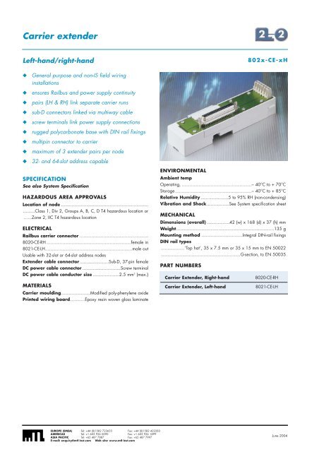
Carrier extenderLeft-hand/right-hand◆◆◆◆◆◆◆◆◆General purpose and non-IS field wiringinstallationsensures Railbus and power supply continuitypairs (LH & RH) link separate carrier runssub-D connectors linked via multiway cablescrew terminals link power supply connectionsrugged polycarbonate base with DIN rail fixingsmultipin connector to carriermaximum of 3 extender pairs per node32- and 64-slot address capableSPECIFICATIONSee also System SpecificationHAZARDOUS AREA APPROVALSLocation of node ...........................................................................Class 1, Div 2, Groups A, B, C, D T4 hazardous location or......Zone 2, IIC T4 hazardous locationELECTRICALRailbus carrier connector ....................................................8020-CE-RH ................................................................female in8021-CE-LH..................................................................male outUsable with 32-slot or 64-slot address nodesExtender cable connector ......................Sub-D, 37-pin femaleDC power cable connector .............................Screw terminalDC power cable conductor size ....................2.5 mm 2 (max.)MATERIALSCarrier moulding......................Modified poly-phenylene oxidePrinted wiring board...........Epoxy resin woven glass laminate802x-CE-xHENVIRONMENTALAmbient tempOperating, .....................................................– 40°C to + 70°CStorage..........................................................– 40°C to + 85°CRelative Humidity .....................5 to 95% RH (non-condensing)Vibration and Shock.................See System specification sheetMECHANICALDimensions (overall) .................42 (w) x 168 (d) x 37 (h) mmWeight..........................................................................135 gMounting method ...............................Integral DIN-rail fixingsDIN rail types..................‘Top hat’, 35 x 7.5 mm or 35 x 15 mm to EN 50022............................................................G-section, to EN 50035PART NUMBERSCarrier Extender, Right-hand8020-CE-RHCarrier Extender, Left-hand8021-CE-LHEUROPE (EMEA) Tel: +44 (0)1582 723633 Fax: +44 (0)1582 422283AMERICAS Tel: +1 603 926 0090 Fax: +1 603 926 1899ASIA PACIFIC Tel: +65 487 7887 Fax: +65 487 7997E-mail: enquiry@mtl-inst.com Web site: www.mtl-inst.comJune 2004


