


You also want an ePaper? Increase the reach of your titles
YUMPU automatically turns print PDFs into web optimized ePapers that Google loves.
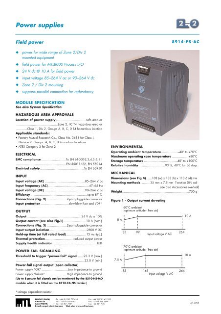
Power suppliesField power8914-PS-AC◆ power for wide range of Zone 2/Div 2mounted equipment◆◆◆◆◆field power for MTL<strong>8000</strong> Process I/O24 V dc @ 10 A for field powerinput voltage 85–264 V ac or 90–264 V dcZone 2 / Div 2 mountingsupports parallel connection for redundancyMODULE SPECIFICATIONSee also System SpecificationHAZARDOUS AREA APPROVALSLocation of power supply .................................safe area or.............................................Zone 2, IIC T4 hazardous area or............Class 1, Div 2, Groups A, B, C, D T4 hazardous locationApplicable standards:• Factory Mutual Research Co., Class No. 3611 for Class I,Division 2, Groups A, B, C, D hazardous locations• ATEX Category 3 for Zone 2ELECTRICALEMC compliance ...........................To EN 61000-2,3,4,5,6,11.......................................................EN 55011/22, EN 55014Electrical safety................................................To EN 60950INPUTInput voltage (AC) ............................................85–264 V acInput frequency (AC).............................................47–65 HzInput voltage (DC) ............................................90–264 V dcEfficiency ..............................................................up to 87 %Connections (Fig. 2) ......................2-part pluggable connectorInput protection...............................slow-blow fuse and VDR*OUTPUTOutput............................................................24 V dc ± 10%Output current (see also Fig.1).........................10 A (nom.)Connections (Fig. 3) ......................2-part pluggable connectorInput-output isolation ........................................2800 V DCHold-up time (at full rated load) ......................15 ms (typ.)Thermal protection...............................reduced output powerSupply health indicator .................................................LEDPOWER-FAIL SIGNALINGThreshold to trigger "power-fail" signal ......23.3 V (max.)...........................................................................22.0 V (min.)Power-fail signal output (open collector)Power supply "OK" .............................Low impedance to groundPower supply "failure"........................High impedance to ground(Up to 8 power fail signals can be monitored by the 8510-NS-MOmodule when it is fitted on the 8718-CA-NS carrier.)ENVIRONMENTALOperating ambient temperature..................–40° to +70°CMaximum operating case temperature ..................+80°CStorage temperature ...................................–40° to +100°CRelative humidity .............................93 %, 40°C for 56 daysMECHANICALDimensions (see Fig 4) ......103 (w) x 138 (h) x 113.6 (d) mmMounting methods .........35 mm x 7.5 mm T-section DIN rail(see also Accessories overleaf)Weight .........................................................................750 gFigure 1 - Output current de-rating8 A7.5 A60°C ambient(optimum attitude - free air)859970°C ambient(optimum attitude - free air)85Input voltage V AC165Input voltage V AC26426410 A10 A*voltage dependent resistorEUROPE (EMEA) Tel: +44 (0)1582 723633 Fax: +44 (0)1582 422283AMERICAS Tel: +1 603 926 0090 Fax: +1 603 926 1899ASIA PACIFIC Tel: +65 487 7887 Fax: +65 487 7997E-mail: enquiry@mtl-inst.com Web site: www.mtl-inst.comJul 2005


