


Create successful ePaper yourself
Turn your PDF publications into a flip-book with our unique Google optimized e-Paper software.
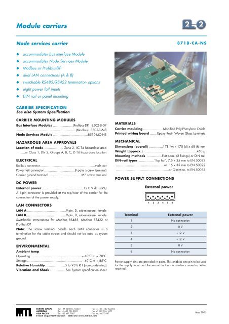
Module carriersNode services carrier8718-CA-NS◆ accommodates Bus Interface Module◆ accommodates Node Services Module◆ Modbus or Profibus-DP◆ dual LAN connections (A & B)◆ switchable RS485/RS422 termination options◆ eight power fail inputs◆ DIN rail or panel mountingCARRIER SPECIFICATIONSee also System SpecificationCARRIER MOUNTING MODULESBus Interface Modules .....................(Profibus-DP) 8502-BI-DP..............................................................(Modbus) 8505-BI-MBNode Services Module .....................................8510-MO-NSHAZARDOUS AREA APPROVALSLocation of node..................... Zone 2, IIC T4 hazardous area.........or Class 1, Div 2, Groups A, B, C, D T4 hazardous locationELECTRICALRailbus connector..........................................................male outPower fail connector ................................8 pairs (screw terminal)Carrier ground terminal...................................M2 screw terminalDC POWERExternal power ............................................12.0 V dc (±5%)A 6-pin connector is provided at the top/rear of the carrier for theconnection of the power supply.LAN CONNECTORSLAN A .........................................9-pin, D, sub-minature, femaleLAN B..........................................9-pin, D, sub-minature, femaleSwitchable terminations for Modbus RS485, Modbus RS422 orProfibus-DPNote: The screw terminal beside each LAN connector is atermination for the cable screen and should not be used as systemground.ENVIRONMENTALAmbient tempOperating ......................................................– 40°C to + 70°CStorage..........................................................– 40°C to + 85°CRelative Humidity .....................5 to 95% RH (non-condensing)Vibration and Shock.................See System specification sheetMATERIALSCarrier moulding .....................Modified Poly-Phenylene OxidePrinted wiring board ........Epoxy Resin Woven Glass LaminateMECHANICALDimensions (overall) ...............178 (w) x 170 (d) x 68 (h) mmWeight (approx.).........................................................450 gMounting methods ................Flat panel (2 fixings) or DIN railDIN-rail types ................‘Top hat’, 7.5 x 35 mm to EN 50022...................................................or 15 x 35 mm to EN 50022........................................................or G-section, to EN 50035POWER SUPPLY CONNECTIONSTerminalExternal power1 2 3 4 5 6External power1 No connection2 0 V3 +12 V4 +12 V5 0 V6 No connectionPower supply pins are provided in pairs. This enables one pin to be usedfor the supply input and the second to loop to another connector, whenrequired.EUROPE (EMEA) Tel: +44 (0)1582 723633 Fax: +44 (0)1582 422283AMERICAS Tel: +1 603 926 0090 Fax: +1 603 926 1899ASIA PACIFIC Tel: +65 487 7887 Fax: +65 487 7997E-mail: enquiry@mtl-inst.com Web site: www.mtl-inst.comMay 2006


