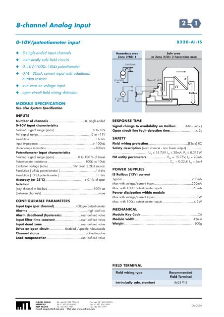
8-channel Analog Input0-10V/potentiometer input8230-AI-IS◆◆8 single-ended input channelsintrinsically safe field circuitsHazardous areaZone 0/Div 1Safe areaor Zone 2/Div 2 hazardous area◆0–10V/100Ω–10kΩ potentiometer250/500 R◆◆◆0/4 - 20mA current input with additionalburden resistortrue zero on voltage inputopen circuit field wiring detection0/4–20mAChannel 1 of 8+–#RailbusMODULE SPECIFICATIONSee also System Specification0 –10VDC+INPUTSNumber of channels .......................................8, single-ended0–10V input characteristicsNominal signal range (span) ..........................................0 to 10VFull signal range..........................................................0 to +11VResolution........................................................................16 bitsInput impedance ...........................................................> 100kΩUnder-range indication ...................................................–100mVPotentiometer input characteristicsNominal signal range (span) ..........................0 to 100 % of travelPotentiometer resistance.........................................100Ω to 10kΩExcitation voltage (nom.) .........................10V (from 2.2kΩ source)Resolution ( ≥1kΩ potentiometer ).......................................14 bitsResolution (100Ω potentiometer ) .......................................11 bitsAccuracy (at 25°C) ..........................................± 0.1% of spanIsolation(any channel to Railbus) .................................................100V ac(between channels)..............................................................noneCONFIGURABLE PARAMETERSInput type (per channel)........................voltage/potentiometerAlarms.................................................................high and lowAlarm deadband (hysteresis).....................user defined valueInput filter time constant ............................user defined valueInput dead zone ..........................................user defined valueDrive on open circuit................ disabled /upscale /downscaleChannel status................................................. active/inactiveLead compensation .....................................user defined valueRESPONSE TIMESignal change to availability on Railbus ..........33ms (max.)Open circuit line fault detection time ............................≤ 5sSAFETYField wiring protection...........................................[EExia] IICSafety description (each channel - non linear output) ......................................................U o ≤ 15.75V, I o ≤ 20mA, P o ≤ 0.315WFM entity parameters......................V oc = 15.75V, I sc = 20mA..............................................................C a = 0.22µF, L a = 5mHPOWER SUPPLIESIS Railbus (12V) currentTypical ...........................................................................200mAMax with voltage/current inputs........................................250mAMax. with 100Ω potentiometer inputs................................350mAPower dissipation within moduleMax with voltage/current inputs.............................................3WMax. with 100Ω potentiometer inputs ..................................4.2WMECHANICALModule Key Code .............................................................C4Module width ...............................................................42mmWeight ............................................................................200gFIELD TERMINALField wiring typeIntrinsically safe, standardRecommendedField Terminal8623-FT-ISEUROPE (EMEA) Tel: +44 (0)1582 723633 Fax: +44 (0)1582 422283AMERICAS Tel: +1 603 926 0090 Fax: +1 603 926 1899ASIA PACIFIC Tel: +65 487 7887 Fax: +65 487 7997E-mail: enquiry@mtl-inst.com Web site: www.mtl-inst.comOct 2006
8-channel Analog InputThermocouple and mV8205-TI-IS◆◆8 input channelsintrinsically safe field circuitsHazardous areaZone 0/Div 1Safe areaor Zone 2/Div 22 hazardous area area◆thermocouple and mV◆cold junction compensation (internal or remote)◆built-in thermocouple linearisation#◆channels independently configurableChannel 1 of 8◆open-circuit field wiring detectionRailbusMODULE SPECIFICATIONSee also System SpecificationmVCJINPUTSNumber of channels ..........................................................8THC inputs .................B,E,J,K,N,R,S or T to EN 60584-1: 1995;................................................W3 and W5 to ASTM E 988-96..................................Russian K and Russian L to rOCT 3044-84.....................................user definable linearisation table, note 1Input typeThermocouples: B 0 to + 1820°CmVE – 270 to + 1000°CJ – 210 to + 1200°CK – 270 to + 1372°CN –270 to + 1300°CR & SRange– 50 to + 1768.1°CT – 270 to + 400°CW3 & W5 0 to + 2315°CRussian K -200 to + 1300°CRussian L -200 to + 800°C– 8 to + 24 mV– 20 to + 60 mV– 33.333 to + 100 mV– 100 to + 100 mVIn addition, see error table in System specification sectionAccuracy (% of span)Tamb mV inputs THC inputs25°C ± 0.05% ± 0.05%+10 to + 40°C ± 0.08% ± 0.1%– 40 to + 70°C ± 0.18% ± 0.3%Temperature drift ..............................< ± 0.003% of span/°CCold junction compensation error* ..< ± 1°C (–40 to +70°C)Resolution ....................................................................16 bitsCommon mode rejection........................> 87dB @ 50/60 HzSeries mode rejection ............................> 50dB @ 50/60 HzCommon mode voltage between channels ......± 5V (max.)Absolute maximum input voltage..............................± 30VIsolation (any channel to Railbus) ........................60V peakNote 1: Consult MTL for support in BIM/configurator.CONFIGURABLE PARAMETERSSensor type .......................................................user selectableAlarms.................................................................high and lowInput dead zone ..........................................user defined valueSelectable input filtering.......off /2 reading avg./running avg.Drive on open circuit fault ......... disabled/upscale/downscaleChannel status ..................................................active/inactiveCold junction compensation .........enable/disable/channel no.RESPONSE TIMEResponse time....................................................600ms (max.)(Analog signal change to availability on Railbus)SAFETYField wiring protection..........................................[EEx ia] IICSafety Description (each channel)Channels 1, 2, 3, 4, 7 and 8, wired as separate IS circuits.........................................Uo = 16.4V, Io = 79mA, Po = 0.33WChannels 5 and 6, wired as separate IS circuits............................................Uo = 1V, Io = 1.1mA, Po = 0.3mW(Input terminals are equivalent to non-energy storing apparatus)FM entity parameters ...........................................................Channels 1, 2, 3, 4, 7 and 8, wired as separate IS circuits..................................Voc = 16.4V, Isc = 63.7mA, Po = 131mWChannels 5 and 6, wired as separate IS circuits.............................................Uo = 1V, Io = 1mA, Po = 0.25mWPOWER SUPPLIESIS Railbus (12V) current...................................120mA (max.)Power dissipation within module .....................1.5W (max.)MECHANICALModule Key Code .............................................................C1Module width ...............................................................42mmWeight ............................................................................245g* Cold junction compensation located in recommended field terminal.FIELD TERMINALField wiring typeIntrinsically safe THCRecommendedField Terminal8625-FT-ISEUROPE (EMEA) Tel: +44 (0)1582 723633 Fax: +44 (0)1582 422283AMERICAS Tel: +1 603 926 0090 Fax: +1 603 926 1899ASIA PACIFIC Tel: +65 487 7887 Fax: +65 487 7997E-mail: enquiry@mtl-inst.com Web site: www.mtl-inst.comOct 2006