


You also want an ePaper? Increase the reach of your titles
YUMPU automatically turns print PDFs into web optimized ePapers that Google loves.
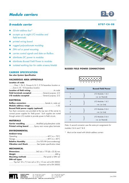
Module carriers8-module carrier◆◆◆◆◆◆◆◆◆32-slot address bus*accepts up to eight I/O modules andfield terminalsprinted wiring boardrugged polycarbonate mouldingDIN rail or panel mountingcarries control signals and data on Railbusdistributes DC power to modulesdistributes Bussed Field Power to modulesisolated earthing bar for cable screens/shieldsCARRIER SPECIFICATIONSee also System SpecificationHAZARDOUS AREA APPROVALSLocation of node.........Class 1, Div 2, Groups A, B, C, D T4 hazardous location or......Zone 2, IIC T4 hazardous locationLocation of field wiring ...........................................As nodeField terminals accepted......................General purpose, 2/2I/O modules accepted ........................ General purpose, 2/2ELECTRICALRailbus connectors....................................female in, male outModule address range.................................................1–32Bussed field power supply (optional)Two 8-pin connectors are provided at the top rear of the carrier toconnect power supplies for ‘field power’. Such supplies are routedthrough certain I/O module to provide power to field circuits.MATERIALSCarrier moulding......................Modified poly-phenylene oxidePrinted wiring board...........Epoxy resin woven glass laminateENVIRONMENTALAmbient tempOperating, .....................................................– 40°C to + 70°CStorage..........................................................– 40°C to + 85°CRelative Humidity .....................5 to 95% RH (non-condensing)Vibration and Shock.................See System specification sheet8707-CA-08BUSSED FIELD POWER CONNECTIONS1 2 3 4 5 6 7 8TerminalBussed Field Power}1 I/O Modules 1 & 22 –ve (or Neutral)}3 I/O Modules 1 & 24 +ve (or Live)}5 I/O Modules 3 & 46 +ve (or Live)}7 I/O Modules 3 & 48 –ve (or Neutral)Note: A second connector uses the same pin assignments formodules 5 & 6 and 7 & 8.* Must not be mixed with 64-slot address carriersMECHANICALDimensions...............................342 (w) x 170 (d) x 22 (h) mmWeight..........................................................................680 gMounting methods ...............................Flat panel or DIN railDIN-rail types........‘Top hat’ 35 x 7.5 mm rail or 35 x 15 mm rail to EN 50022........................................................G-section rail to EN 50035EUROPE (EMEA) Tel: +44 (0)1582 723633 Fax: +44 (0)1582 422283AMERICAS Tel: +1 603 926 0090 Fax: +1 603 926 1899ASIA PACIFIC Tel: +65 487 7887 Fax: +65 487 7997E-mail: enquiry@mtl-inst.com Web site: www.mtl-inst.comJune 2004


