


Create successful ePaper yourself
Turn your PDF publications into a flip-book with our unique Google optimized e-Paper software.
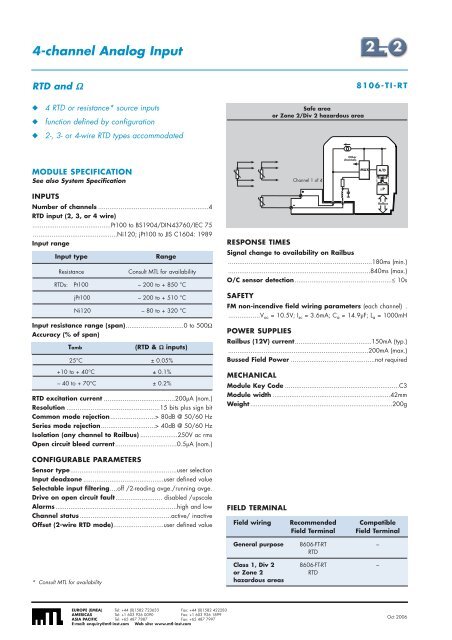
4-channel Analog InputRTD and Ω8106-TI-RT◆◆◆4 RTD or resistance* source inputsfunction defined by configuration2-, 3- or 4-wire RTD types accommodatedSafe areaor Zone 2/Div 2 hazardous areaOtherchannelsMODULE SPECIFICATIONSee also System SpecificationINPUTSNumber of channels ...........................................................4RTD input (2, 3, or 4 wire)..........................................Pt100 to BS1904/DIN43760/IEC 75.............................................Ni120; jPt100 to JIS C1604: 1989Input rangeInput typeResistanceInput resistance range (span)...............................0 to 500ΩAccuracy (% of span)RTD excitation current ......................................200µA (nom.)Resolution ..................................................15 bits plus sign bitCommon mode rejection........................> 80dB @ 50/60 HzSeries mode rejection.............................> 40dB @ 50/60 HzIsolation (any channel to Railbus) ....................250V ac rmsOpen circuit bleed current.................................0.5µA (nom.)CONFIGURABLE PARAMETERSConsult MTL for availabilityRTDs: Pt100 – 200 to + 850 °CjPt100 – 200 to + 510 °CNi120 – 80 to + 320 °CTambRange(RTD & Ω inputs)25°C ± 0.05%+10 to + 40°C ± 0.1%– 40 to + 70°C ± 0.2%Sensor type.........................................................user selectionInput deadzone ...........................................user defined valueSelectable input filtering....off /2-reading avge./running avge.Drive on open circuit fault......................... disabled /upscaleAlarms.................................................................high and lowChannel status.................................................active/ inactiveOffset (2-wire RTD mode)...........................user defined valueRESPONSE TIMESSignal change to availability on Railbus.............................................................................180ms (min.)............................................................................840ms (max.)O/C sensor detection....................................................≤ 10sSAFETYFM non-incendive field wiring parameters (each channel) ..................V oc = 10.5V; I sc = 3.6mA; C a = 14.9µF; L a = 1000mHPOWER SUPPLIESRailbus (12V) current.........................................150mA (typ.)...........................................................................200mA (max.)Bussed Field Power .............................................not requiredMECHANICALChannel 1 of 4Module Key Code .............................................................C3Module width ...............................................................42mmWeight ............................................................................200gFIELD TERMINALMUXA/DµPRailbusField wiring Recommended CompatibleField Terminal Field TerminalGeneral purpose 8606-FT-RT –RTD* Consult MTL for availabilityClass 1, Div 2 8606-FT-RT –or Zone 2RTDhazardous areasEUROPE (EMEA) Tel: +44 (0)1582 723633 Fax: +44 (0)1582 422283AMERICAS Tel: +1 603 926 0090 Fax: +1 603 926 1899ASIA PACIFIC Tel: +65 487 7887 Fax: +65 487 7997E-mail: enquiry@mtl-inst.com Web site: www.mtl-inst.comOct 2006


