


You also want an ePaper? Increase the reach of your titles
YUMPU automatically turns print PDFs into web optimized ePapers that Google loves.
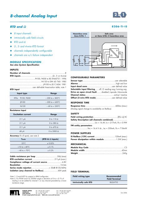
8-channel Analog InputRTD and Ω8206-TI-IS◆◆8 input channelsintrinsically safe field circuitsHazardous areaZone 0/Div 1Safe areaor Zone 2/Div 2 hazardous area◆RTD and Ω◆2-, 3- and 4-wire RTD format◆◆channels independently configurablechannels are o/c failure independentChannel 1 of 8#MODULE SPECIFICATIONSee also System SpecificationINPUTSNumber of channels ...........................................................8RTD inputs.......................................................(2-, 3- or 4-wire)...........................................Pt100, Pt500 to BS EN60751: 1996.....................................................Ni120 to DIN 43 760: 1985.........................................................jPt100 to JIS C1604: 1981......................................user definable linearisation table, note 1RTD inputInput typeRTDs: Pt100, Pt500 – 200 to + 850°CResistance inputjPt100 – 200 to + 650°CNi120 – 60 to + 250°CExcitation currentAccuracy (% of span), see note 2Range211 µA 0 to 110 Ω211 µA 0 to 280 Ω211 µA 0 to 470 Ω48 µA 0 to 2000 ΩTambRange(RTD & Ω inputs)25°C ± 0.05%+10 to + 40°C ± 0.1%– 40 to + 70°C ± 0.2%Cable resistance per loop .....................................50Ω (max)RTD excitation current ......................................211µA (nom.)Compliance voltage of current source .........................6.8VResolution ....................................................................16 bitsSeries mode rejection..............................> 50dB @ 50/60HzIsolation (any channel to Railbus).........................60V peakRailbusCONFIGURABLE PARAMETERSSensor type .......................................................user selectableAlarms.................................................................high and lowInput dead zone ..........................................user defined valueSelectable input filtering.......off /2 reading avg./running avg.Drive on open circuit fault....... disabled /upscale /downscaleChannel status.................................................active/ inactiveOffset (2-wire RTD mode)...........................user defined valueRESPONSE TIMEResponse time....................................................600ms (max.)(Analog signal change to availability on Railbus)SAFETYField wiring protection..........................................[EEx ia] IICSafety Description (all channels combined).................................................................Uo = 16.4V, Io = 217mA, Po = 0.9WFM entity parameters............................Voc = 16.4 V dc , Isc = 350mA, Po = 718mWPOWER SUPPLIESIS Railbus (12V) current...................................120mA (max.)Power dissipation within module .....................1.5W (max.)MECHANICALModule Key Code .............................................................C3Module width ...............................................................42mmWeight ............................................................................245gFIELD TERMINALNote 1: Consult MTL for support in BIM/configurator.Note 2: For Pt500 and 0 to 2000Ω ranges a deviation of 0 to + 0.1% ofreading is to be added for channel 1 or any channel preceded by a lowerresistance range.Field wiring typeIntrinsically safe RTDRecommendedField Terminal8626-FT-ISEUROPE (EMEA) Tel: +44 (0)1582 723633 Fax: +44 (0)1582 422283AMERICAS Tel: +1 603 926 0090 Fax: +1 603 926 1899ASIA PACIFIC Tel: +65 487 7887 Fax: +65 487 7997E-mail: enquiry@mtl-inst.com Web site: www.mtl-inst.comOct 2006


