Technical Provisions for Mode S Services and Extended Squitter
Technical Provisions for Mode S Services and Extended Squitter
Technical Provisions for Mode S Services and Extended Squitter

Create successful ePaper yourself
Turn your PDF publications into a flip-book with our unique Google optimized e-Paper software.
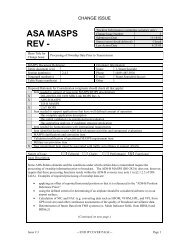
A-50 <strong>Technical</strong> <strong>Provisions</strong> <strong>for</strong> <strong>Mode</strong> S <strong>Services</strong> <strong>and</strong> <strong>Extended</strong> <strong>Squitter</strong><br />
MB FIELD<br />
DRAFT - Working Paper ASP TSGWP11-01 <strong>for</strong> review by the TSG during the meeting in June 2011 in Paris<br />
1 MSB<br />
2<br />
3<br />
4 BDS Code 1,0<br />
5<br />
6<br />
7<br />
8 LSB<br />
9 Continuation flag (see 9)<br />
10<br />
11<br />
12 RESERVED<br />
13<br />
14<br />
15 Overlay Comm<strong>and</strong> Capability (OCC) (see 19)<br />
16 Reserved <strong>for</strong> ACAS (see 1)<br />
17 MSB<br />
18<br />
19<br />
20 <strong>Mode</strong> S subnetwork version number (see 12)<br />
21<br />
22<br />
23 LSB<br />
24 Transponder enhanced protocol indicator (see 4)<br />
25 <strong>Mode</strong> S specific services capability (see 2)<br />
26 MSB<br />
27 Uplink ELM average throughput capability (see 13)<br />
28 LSB<br />
29 Downlink ELM: throughput capability of downlink ELM<br />
30 containing the maximum number of ELM segments that the<br />
transponder can deliver in response to a single requesting<br />
31<br />
interrogation (UF = 24). (see 14)<br />
32<br />
33 Aircraft identification capability (see 11)<br />
34 <strong>Squitter</strong> capability subfield (SCS) (see 5)<br />
35 Surveillance identifier code (SIC) (see 6)<br />
36 Common usage GICB capability report (see 7)<br />
37<br />
38 RESERVED FOR ACAS (see 1)<br />
39<br />
40<br />
41 MSB<br />
42<br />
43<br />
44<br />
45<br />
46<br />
47 Bit array indicating the support status of DTE<br />
48 Sub-addresses 0 to 1 5 (see 3 <strong>and</strong> 8)<br />
49<br />
50<br />
51<br />
52<br />
53<br />
54<br />
55<br />
56 LSB<br />
Table A-2-16. BDS code 1,0 — Data link capability report<br />
PURPOSE: To report the data link capability of the <strong>Mode</strong> S<br />
transponder/data link installation.<br />
The coding of this register shall con<strong>for</strong>m to:<br />
1) Annex 10, Volume IV, §3.1.2.6.10.2 <strong>and</strong> §4.3.8.4.2.2.2.<br />
2) When bit 25 is set to 1, it shall indicate that at least one <strong>Mode</strong> S<br />
specific service (other than GICB services related to registers 0216,<br />
0316, 0416, 1016, 1716 to 1C16, 2016 <strong>and</strong> 3016) is supported <strong>and</strong> the<br />
particular capability reports shall be checked.<br />
Note.— Registers accessed by BDS Codes 0,2; 0,3; 0,4; 1,0; 1,7<br />
to 1,C; 2,0 <strong>and</strong> 3,0 do not affect the setting of bit 25.<br />
3) Starting from the MSB, each subsequent bit position shall represent<br />
the DTE subaddress in the range from 0 to 15.<br />
4) The enhanced protocol indicator shall denote a Level 5 transponder<br />
when set to 1, <strong>and</strong> a Level 2 to 4 transponder when set to 0.<br />
5) The squitter capability subfield (SCS) shall be set to 1 if both registers<br />
0516 <strong>and</strong> 0616 have been updated within the last ten, plus or minus<br />
one, seconds. Otherwise, it shall be set to 0.<br />
Note.— Registers 0516 <strong>and</strong> 0616 are used <strong>for</strong> the extended squitter<br />
Airborne <strong>and</strong> surface position reports, respectively.<br />
6) The surveillance identifier code (SIC) bit shall be interpreted as<br />
follows:<br />
0 = no surveillance identifier code capability<br />
1 = surveillance identifier code capability<br />
7) Bit 36 shall be toggled each time the common usage GICB capability<br />
report (register 1716) changes. To avoid the generation of too many<br />
broadcast capability report changes, register 1716 shall be sampled at<br />
approximately one minute intervals to check <strong>for</strong> changes.<br />
8) The current status of the on-board DTE shall be periodically reported<br />
to the GDLP by on-board sources. Since a change in this field results<br />
in a broadcast of the capability report, status inputs shall be sampled<br />
at approximately one minute intervals.<br />
Draft<br />
9) In order to determine the extent of any continuation of the data link<br />
capability report (into those registers reserved <strong>for</strong> this purpose:<br />
register 1116 to register 1616), bit 9 shall be reserved as a continuation<br />
flag to indicate if the subsequent register shall be extracted. For<br />
example: upon detection of bit 9 = 1 in register 1016, then register<br />
1116 shall be extracted. If bit 9 = 1, in register 1116, then register 1216<br />
shall be extracted, <strong>and</strong> so on (up to register 1616). Note that if bit<br />
9 = 1 in register 1616, then this shall be considered as an error<br />
condition.<br />
10 The <strong>Mode</strong> S transponder may update bits 1-8, 16, 33, 35 <strong>and</strong> 37-40<br />
independent of the ADLP. These bits are provided by the<br />
transponder when the data link capability report is broadcast as a<br />
result of a transponder detected change in capability reported by the<br />
ADLP (§3.1.2 of Annex 10 Volume IV).<br />
(Requirements are continued on the next page)<br />
DRAFT - Working Paper ASP TSGWP11-01 <strong>for</strong> review by the TSG during the meeting in June 2011 in Paris