TC1765_ds_v12 (TC1765_ds_v12_1202.pdf) - Infineon
TC1765_ds_v12 (TC1765_ds_v12_1202.pdf) - Infineon
TC1765_ds_v12 (TC1765_ds_v12_1202.pdf) - Infineon
- TAGS
- infineon
- www.infineon.com

Create successful ePaper yourself
Turn your PDF publications into a flip-book with our unique Google optimized e-Paper software.
Preliminary<br />
TwinCAN Interface<br />
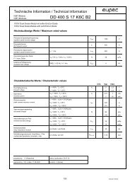
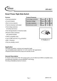
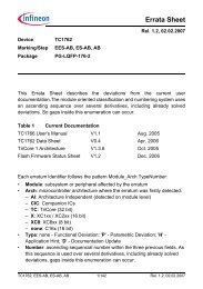
Figure 7 shows a global view of the functional blocks of the TwinCAN module.<br />
Clock<br />
Control<br />
Address<br />
Decoder<br />
Interrupt<br />
Control<br />
f CAN<br />
SR0<br />
SR1<br />
SR2<br />
SR3<br />
SR4<br />
SR5<br />
SR6<br />
SR7<br />
TwinCAN Module Kernel<br />
Interrupt<br />
Control<br />
Bitstream<br />
Processor<br />
Message<br />
Buffers<br />
Timing<br />
Control<br />
Error<br />
Handling<br />
Control<br />
TXDC0<br />
RXDC0<br />
TXDC1<br />
RXDC1<br />
Port<br />
Control<br />
Figure 7 General Block Diagram of the TwinCAN Module<br />
<strong>TC1765</strong><br />
P0.13 /<br />
TXDCAN0<br />
P0.12 /<br />
RXDCAN0<br />
P0.15 /<br />
TXDCAN1<br />
P0.14 /<br />
RXDCAN1<br />
MCB05059<br />
The TwinCAN module has four I/O lines located at Port 0. The TwinCAN module is<br />
further supplied by a clock control, interrupt control, address decoding, and port control<br />
logic.<br />
The TwinCAN module contains two Full-CAN nodes operating independently or<br />
exchanging data and remote frames via a gateway function. Transmission and reception<br />
of CAN frames are handled in accordance to CAN specification V2.0 part B (active).<br />
Each of the two Full-CAN nodes can receive and transmit standard frames with 11-bit<br />
identifiers as well as with extended frames with 29-bit identifiers.<br />
Both CAN nodes share the TwinCAN module’s resources to optimize the CAN bus traffic<br />
handling and to minimize the CPU load. The flexible combination of Full-CAN<br />
functionality and the FIFO architecture reduces the efforts to fulfill the real-time<br />
requirements of complex embedded control applications. Improved CAN bus monitoring<br />
functionality as well as the increased number of message objects permit precise and<br />
convenient CAN bus traffic handling.<br />
Depending on the application, each of the thirty-two message objects can be individually<br />
assigned to one of the two CAN nodes. Gateway functionality allows automatic data<br />
exchange between two separate CAN bus systems, which decreases CPU load and<br />
improves the real time behavior of the entire system.<br />
Data Sheet 23 V1.2, 2002-12