TC1765_ds_v12 (TC1765_ds_v12_1202.pdf) - Infineon
TC1765_ds_v12 (TC1765_ds_v12_1202.pdf) - Infineon
TC1765_ds_v12 (TC1765_ds_v12_1202.pdf) - Infineon
- TAGS
- infineon
- www.infineon.com

Create successful ePaper yourself
Turn your PDF publications into a flip-book with our unique Google optimized e-Paper software.
Preliminary<br />
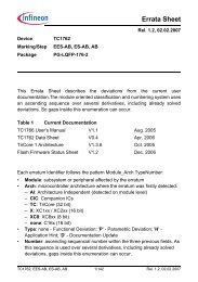
±2.0<br />
ns<br />
D N<br />
±1.8<br />
±1.6<br />
±1.4<br />
±1.2<br />
±1.0<br />
0<br />
D N<br />
P<br />
K<br />
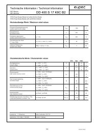
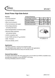
f SYS = 20 MHz (K = 8)<br />
f SYS = 25 MHz (K = 8)<br />
f SYS = 33 MHz (K = 6)<br />
f SYS = 40 MHz (K = 4)<br />
1 2 3 4 5 6<br />
= M ax. jitter<br />
= Number of consecutive f SYS perio<strong>ds</strong><br />
= K-divider of PLL<br />
MCD05141_mod<br />
<strong>TC1765</strong><br />
Figure 29 Approximated Maximum Accumulated PLL Jitter for Typical System<br />
Clock Frequencies f SYS<br />
Note: For safe clock generation and PLL operation the definitions and restrictions as<br />
defined at pages 50, 51, and 72 must be regarded.<br />
Data Sheet 75 V1.2, 2002-12<br />
P<br />
7