TC1765_ds_v12 (TC1765_ds_v12_1202.pdf) - Infineon
TC1765_ds_v12 (TC1765_ds_v12_1202.pdf) - Infineon
TC1765_ds_v12 (TC1765_ds_v12_1202.pdf) - Infineon
- TAGS
- infineon
- www.infineon.com

You also want an ePaper? Increase the reach of your titles
YUMPU automatically turns print PDFs into web optimized ePapers that Google loves.
Preliminary<br />
Testing Waveforms<br />
TA = -40 °C to +125 °C; Frequency: max. 40 MHz;<br />
Class A Pins: VDDP813 = 3.0 to 5.25 V; VSS = 0 V;<br />
V IHmin<br />
V ILmax<br />
V OHmin<br />
V OLmax<br />
Test Points<br />
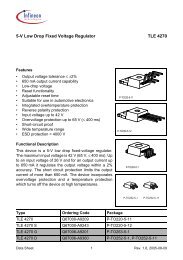
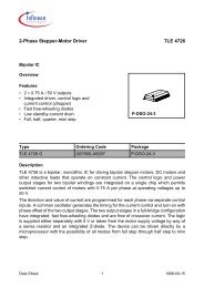
Figure 24 Testing Waveforms for Class A Pins<br />
Class B and Class C Pins: V DD = 2.30 to 2.75 V; V SS = 0 V;<br />
V DDOSC = 2.30 to 2.75 V; V SSOSC = 0 V;<br />
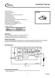
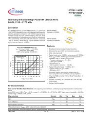
Figure 25 Testing Waveforms for Class B and Class C Pins<br />
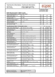
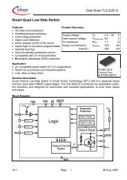
Figure 26 Tri-State Testing Waveforms for Class B Pins<br />
V OHmin<br />
V OLmax<br />
MCT04880<br />
AC inputs during testing are driven with VIHmin for a logic 1 and VILmax for a logic 0.<br />
Timing measurements are made at VOHmin for a logic 1 and VOLmax for a logic 0.<br />
Input and Output Low/High max./min. voltages are defined at Page 60.<br />
V IHmin<br />
V ILmax<br />
V DD / 2 Test Points V DD / 2<br />
MCT04881<br />
AC inputs during testing are driven with V IHmin for a logic 1 and V ILmax for a logic 0.<br />
Timing measurements are made at V DD /2 for a logic 1 and for a logic 0.<br />
Input Low/High max./min. voltages are defined at Page 61 and Page 68.<br />
V Load + 0.1 V V OH - 0.1 V<br />
Timing<br />
Reference<br />
Points<br />
V Load - 0.1 V V OL - 0.1 V<br />
MCT05074<br />
For timing purposes a port pin is no longer floating when a 100 mV change from load<br />
voltage occurs, but begins to float when a 100 mV change from the loaded V OH/V OL<br />
level occurs (I OH/I OL = 15 mA).<br />
<strong>TC1765</strong><br />
Data Sheet 71 V1.2, 2002-12