Fravol Smart Series Edgebander Manual & Parts List
Fravol Smart Series Edgebander Manual & Parts List
Fravol Smart Series Edgebander Manual & Parts List

You also want an ePaper? Increase the reach of your titles
YUMPU automatically turns print PDFs into web optimized ePapers that Google loves.
USER’S MANUAL AND MAINTENANCE<br />
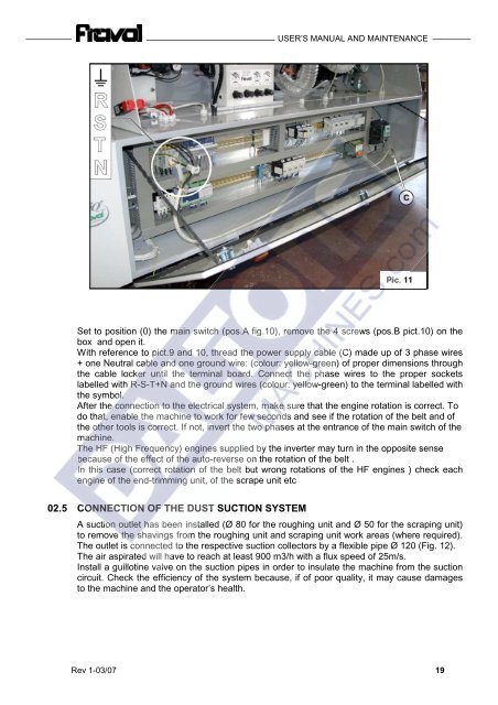
Set to position (0) the main switch (pos.A fig.10), remove the 4 screws (pos.B pict.10) on the<br />
box and open it.<br />
With reference to pict.9 and 10, thread the power supply cable cable (C) made up of 3 3 phase wires<br />
+ + one one Neutral Neutral cable and one ground wire: (colour: yellow-green) of proper dimensions through<br />
the cable locker until the terminal board. Connect the phase wires to the proper sockets<br />
labelled with R-S-T+N and the ground wires wires (colour: yellow-green) yellow-green) to to the the terminal labelled with<br />
the symbol.<br />
After the connection to the electrical system, make sure that the engine engine rotation is correct. To<br />
do do that, enable the machine to work for few seconds seconds and see if the the rotation of of the belt and of<br />
the other tools is correct. If not, invert the the two phases at the the entrance of the the main switch of the<br />
machine.<br />
The HF (High Frequency) engines supplied by the inverter may turn in in the opposite sense<br />
because of the effect of the auto-reverse on the rotation rotation of the belt .<br />
In this case (correct rotation of the belt but wrong wrong rotations rotations of the HF HF engines ) check check each<br />
engine engine of the end-trimming unit, of the scrape unit etc<br />
02.5 CONNECTION OF THE DUST SUCTION SYSTEM<br />
Pic. 11<br />
A suction outlet has been installed (Ø 80 for the roughing unit and Ø 50 for the scraping unit)<br />
to remove the shavings shavings from the roughing roughing unit and scraping unit work areas areas (where required).<br />
The outlet is connected to the respective respective suction collectors by a flexible pipe Ø 120 (Fig. 12).<br />
The air aspirated will will have to reach reach at least 900 m3/h with a flux speed of 25m/s. 25m/s.<br />
Install Install a guillotine valve on the the suction pipes pipes in order order to insulate the machine from the the suction<br />
circuit. Check the efficiency of the system because, if of poor quality, it may cause damages<br />
to the machine and the operator’s health.<br />
Rev 1-03/07 19