

Start-Up, Operation, and Maintenance Instructions
Start-Up, Operation, and Maintenance Instructions
Start-Up, Operation, and Maintenance Instructions

You also want an ePaper? Increase the reach of your titles
YUMPU automatically turns print PDFs into web optimized ePapers that Google loves.
7<br />
6<br />
5<br />
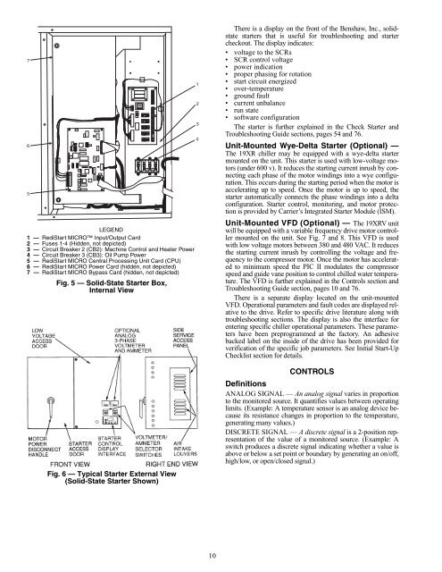
LEGEND<br />
1 — Redi<strong>Start</strong> MICRO Input/Output Card<br />
2 — Fuses 1-4 (Hidden, not depicted)<br />
3 — Circuit Breaker 2 (CB2): Machine Control <strong>and</strong> Heater Power<br />
4 — Circuit Breaker 3 (CB3): Oil Pump Power<br />
5 — Redi<strong>Start</strong> MICRO Central Processing Unit Card (CPU)<br />
6 — Redi<strong>Start</strong> MICRO Power Card (hidden, not depicted)<br />
7 — Redi<strong>Start</strong> MICRO Bypass Card (hidden, not depicted)<br />
Fig. 5 — Solid-State <strong>Start</strong>er Box,<br />
Internal View<br />
Fig. 6 — Typical <strong>Start</strong>er External View<br />
(Solid-State <strong>Start</strong>er Shown)<br />
1<br />
2<br />
3<br />
4<br />
10<br />
There is a display on the front of the Benshaw, Inc., solidstate<br />
starters that is useful for troubleshooting <strong>and</strong> starter<br />
checkout. The display indicates:<br />
voltage to the SCRs<br />
SCR control voltage<br />
power indication<br />
proper phasing for rotation<br />
start circuit energized<br />
over-temperature<br />
ground fault<br />
current unbalance<br />
run state<br />
software configuration<br />
The starter is further explained in the Check <strong>Start</strong>er <strong>and</strong><br />
Troubleshooting Guide sections, pages 54 <strong>and</strong> 76.<br />
Unit-Mounted Wye-Delta <strong>Start</strong>er (Optional) —<br />
The 19XR chiller may be equipped with a wye-delta starter<br />
mounted on the unit. This starter is used with low-voltage motors<br />
(under 600 v). It reduces the starting current inrush by connecting<br />
each phase of the motor windings into a wye configuration.<br />
This occurs during the starting period when the motor is<br />
accelerating up to speed. Once the motor is up to speed, the<br />
starter automatically connects the phase windings into a delta<br />
configuration. <strong>Start</strong>er control, monitoring, <strong>and</strong> motor protection<br />
is provided by Carrier’s Integrated <strong>Start</strong>er Module (ISM).<br />
Unit-Mounted VFD (Optional) — The 19XRV unit<br />
will be equipped with a variable frequency drive motor controller<br />
mounted on the unit. See Fig. 7 <strong>and</strong> 8. This VFD is used<br />
with low voltage motors between 380 <strong>and</strong> 480 VAC. It reduces<br />
the starting current inrush by controlling the voltage <strong>and</strong> frequency<br />
to the compressor motor. Once the motor has accelerated<br />
to minimum speed the PIC II modulates the compressor<br />
speed <strong>and</strong> guide vane position to control chilled water temperature.<br />
The VFD is further explained in the Controls section <strong>and</strong><br />
Troubleshooting Guide section, pages 10 <strong>and</strong> 76.<br />
There is a separate display located on the unit-mounted<br />
VFD. <strong>Operation</strong>al parameters <strong>and</strong> fault codes are displayed relative<br />
to the drive. Refer to specific drive literature along with<br />
troubleshooting sections. The display is also the interface for<br />
entering specific chiller operational parameters. These parameters<br />
have been preprogrammed at the factory. An adhesive<br />
backed label on the inside of the drive has been provided for<br />
verification of the specific job parameters. See Initial <strong>Start</strong>-<strong>Up</strong><br />
Checklist section for details.<br />
CONTROLS<br />
Definitions<br />
ANALOG SIGNAL — An analog signal varies in proportion<br />
to the monitored source. It quantifies values between operating<br />
limits. (Example: A temperature sensor is an analog device because<br />
its resistance changes in proportion to the temperature,<br />
generating many values.)<br />
DISCRETE SIGNAL — A discrete signal is a 2-position representation<br />
of the value of a monitored source. (Example: A<br />
switch produces a discrete signal indicating whether a value is<br />
above or below a set point or boundary by generating an on/off,<br />
high/low, or open/closed signal.)


