

Start-Up, Operation, and Maintenance Instructions
Start-Up, Operation, and Maintenance Instructions
Start-Up, Operation, and Maintenance Instructions

Create successful ePaper yourself
Turn your PDF publications into a flip-book with our unique Google optimized e-Paper software.
stop the chiller when a specific time period on the ice<br />
build schedule is not set for ice build.<br />
4. Entering Chilled Water Temperature <strong>and</strong> ICE BUILD<br />
Contacts — Compressor operation terminates when the<br />
ICE BUILD TERMINATION parameter is set to<br />
2 (BOTH) <strong>and</strong> the conditions described above in items<br />
2 <strong>and</strong> 3 for entering chilled water temperature <strong>and</strong> remote<br />
contacts have occurred.<br />
NOTE: It is not possible to override the CHILLER START/<br />
STOP, CONTROL POINT, <strong>and</strong> ACTIVE DEMAND LIMIT<br />
variables from CCN devices (with a priority 4 or greater) during<br />
the ice build period. However, a CCN device can override<br />
these settings during 2-chiller lead/lag operation.<br />
RETURN TO NON-ICE BUILD OPERATIONS — The ice<br />
build function forces the chiller to start, even if all other schedules<br />
indicate that the chiller should stop. When the ice build<br />
function terminates, the chiller returns to normal temperature<br />
control <strong>and</strong> start/stop schedule operation. The CHILLER<br />
START/STOP <strong>and</strong> CONTROL POINT return to normal operation.<br />
If the CHILLER START/STOP or CONTROL POINT has<br />
been forced (with a device of less than 4 priority) before the ice<br />
build function started, when the ice build function ends, the<br />
previous forces (of less than 4 priority) are not automatically<br />
restored.<br />
Attach to Network Device Control — The Service<br />
menu includes the ATTACH TO NETWORK DEVICE<br />
screen. From this screen, the operator can:<br />
enter the time schedule number (if changed) for<br />
OCCPC03S, as defined in the NET_OPT screen<br />
attach the CVC/ICVC to any CCN device, if the chiller<br />
has been connected to a CCN network. This may include<br />
other PIC-controlled chillers.<br />
upgrade software<br />
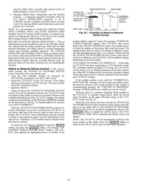
Figure 24 shows the ATTACH TO NETWORK DEVICE<br />
screen. The LOCAL parameter is always the CVC/ICVC module<br />
address of the chiller on which it is mounted. Whenever the<br />
controller identification of the CVC/ICVC changes, the change<br />
is reflected automatically in the BUS <strong>and</strong> ADDRESS columns<br />
for the local device. See Fig. 18. Default address for local device<br />
is BUS 0 ADDRESS 1.<br />
When the ATTACH TO NETWORK DEVICE screen is accessed,<br />
information can not be read from the CVC/ICVC on<br />
any device until one of the devices listed on that screen is attached.<br />
The CVC/ICVC erases information about the module<br />
to which it was attached to make room for information on another<br />
device. Therefore, a CCN module must be attached when<br />
this screen is entered.<br />
To attach any CCN device, highlight it using the SELECT<br />
softkey <strong>and</strong> press the ATTACH softkey. The message “UP-<br />
LOADING TABLES, PLEASE WAIT” displays. The CVC/<br />
ICVC then uploads the highlighted device or module. If the<br />
44<br />
module address cannot be found, the message “COMMUNI-<br />
CATION FAILURE” appears. The CVC/ICVC then reverts<br />
back to the ATTACH TO DEVICE screen. Try another device<br />
or check the address of the device that would not attach. The<br />
upload process time for each CCN module is different. In general,<br />
the uploading process takes 1 to 2 minutes. Before leaving<br />
the ATTACH TO NETWORK DEVICE screen, select the local<br />
device. Otherwise, the CVC/ICVC will be unable to display<br />
information on the local chiller.<br />
ATTACHING TO OTHER CCN MODULES — If the chiller<br />
CVC/ICVC has been connected to a CCN Network or other<br />
PIC controlled chillers through CCN wiring, the CVC/ICVC<br />
can be used to view or change parameters on the other controllers.<br />
Other PIC II chillers can be viewed <strong>and</strong> set points changed<br />
(if the other unit is in CCN control), if desired, from this particular<br />
CVC/ICVC module.<br />
If the module number is not valid, the “COMMUNICA-<br />
TION FAILURE” message will show <strong>and</strong> a new address number<br />
must be entered or the wiring checked. If the module is<br />
communicating properly, the “UPLOAD IN PROGRESS”<br />
message will flash <strong>and</strong> the new module can now be viewed.<br />
Whenever there is a question regarding which module on<br />
the CVC/ICVC is currently being shown, check the device<br />
name descriptor on the upper left h<strong>and</strong> corner of the CVC/<br />
ICVC screen. See Fig. 24.<br />
When the CCN device has been viewed, the ATTACH TO<br />
NETWORK DEVICE table should be used to attach to the PIC<br />
that is on the chiller. Move to the ATTACH TO NETWORK<br />
DEVICE table (LOCAL should be highlighted) <strong>and</strong> press the<br />
ATTACH<br />
Fig. 24 — Example of Attach to Network<br />
Device Screen<br />
softkey to upload the LOCAL device. The CVC/<br />
ICVC for the 19XR will be uploaded <strong>and</strong> default screen will<br />
display.<br />
NOTE: The CVC/ICVC will not automatically reattach to the<br />
local module on the chiller. Press the ATTACH softkey to<br />
attach to the LOCAL device <strong>and</strong> view the chiller operation.


