

Start-Up, Operation, and Maintenance Instructions
Start-Up, Operation, and Maintenance Instructions
Start-Up, Operation, and Maintenance Instructions

Create successful ePaper yourself
Turn your PDF publications into a flip-book with our unique Google optimized e-Paper software.
(see wiring diagrams or certified drawings). The temperature<br />
sensor must be wired to terminal J4-13 <strong>and</strong> J4-14. To configure<br />
Reset Type 2, enter the temperature of the remote sensor at the<br />
point where no temperature reset will occur (REMOTE TEMP<br />
–> NO RESET). Next, enter the temperature at which the full<br />
amount of reset will occur (REMOTE TEMP –> FULL<br />
RESET). Then, enter the maximum amount of reset required to<br />
operate the chiller (DEGREES RESET). Reset Type 2 can now<br />
be activated.<br />
RESET TYPE 3 — Reset Type 3 is an automatic chilled water<br />
temperature reset based on cooler temperature difference.<br />
Reset Type 3 adds ± 30° F (± 16° C) based on the temperature<br />
difference between the entering <strong>and</strong> leaving chilled water<br />
temperature.<br />
To configure Reset Type 3, enter the chilled water temperature<br />
difference (the difference between entering <strong>and</strong> leaving<br />
chilled water) at which no temperature reset occurs (CHW<br />
DELTA T –> NO RESET). This chilled water temperature difference<br />
is usually the full design load temperature difference.<br />
Next, enter the difference in chilled water temperature at which<br />
the full amount of reset occurs (CHW DELTA T –> FULL RE-<br />
SET). Finally, enter the amount of reset (DEGREES RESET).<br />
Reset Type 3 can now be activated.<br />
Dem<strong>and</strong> Limit Control Option — The dem<strong>and</strong> limit<br />
control option (20 mA DEMAND LIMIT OPT) is externally<br />
controlled by a 4 to 20 mA or 1 to 5 vdc signal from an energy<br />
management system (EMS). The option is set up on the<br />
RAMP_DEM screen. When enabled, 4 mA is the 100% dem<strong>and</strong><br />
set point with an operator-configured minimum dem<strong>and</strong><br />
at a 20 mA set point (DEMAND LIMIT AT 20 mA).<br />
The auto. dem<strong>and</strong> limit is hardwired to terminals J5-1 (–)<br />
<strong>and</strong> J5-2 (+) on the CCM. Switch setting number 1 on SW2<br />
will determine the type of input signal. With the switch set at<br />
the ON position the input is configured for an externally powered<br />
4 to 20 mA signal. With the switch in the OFF position the<br />
input is configured for an external 1 to 5 vdc signal.<br />
Surge Prevention Algorithm (Fixed Speed<br />
Chiller) — This is an operator-configurable feature that can<br />
determine if lift conditions are too high for the compressor <strong>and</strong><br />
then take corrective action. Lift is defined as the difference between<br />
the pressure at the impeller eye <strong>and</strong> at the impeller<br />
discharge. The maximum lift a particular impeller wheel can<br />
perform varies with the gas flow across the impeller <strong>and</strong> the<br />
size of the wheel.<br />
A surge condition occurs when the lift becomes so high the<br />
gas flow across the impeller reverses. This condition can eventually<br />
cause chiller damage. The surge prevention algorithm<br />
notifies the operator that chiller operating conditions are marginal<br />
<strong>and</strong> to take action to help prevent chiller damage such as<br />
lowering entering condenser water temperature.<br />
The surge prevention algorithm first determines if corrective<br />
action is necessary. The algorithm checks 2 sets of operator-configured<br />
data points, the minimum load points (MIN.<br />
LOAD POINT [T1,P1]) <strong>and</strong> the full load points (FULL LOAD<br />
POINT [T2,P2]). These points have default settings as defined<br />
on the OPTIONS screen or on Table 4.<br />
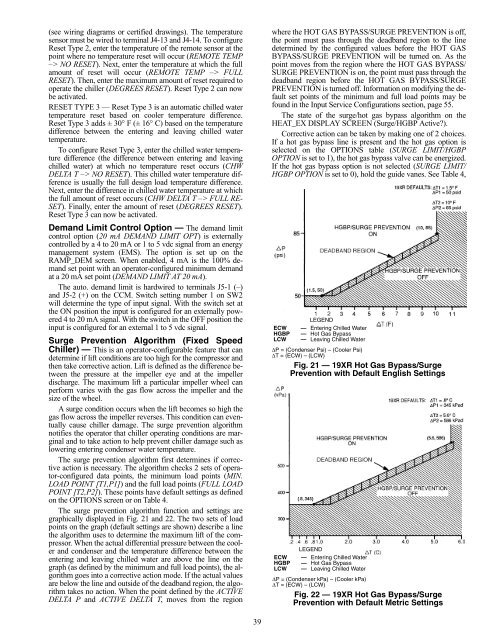
The surge prevention algorithm function <strong>and</strong> settings are<br />
graphically displayed in Fig. 21 <strong>and</strong> 22. The two sets of load<br />
points on the graph (default settings are shown) describe a line<br />
the algorithm uses to determine the maximum lift of the compressor.<br />
When the actual differential pressure between the cooler<br />
<strong>and</strong> condenser <strong>and</strong> the temperature difference between the<br />
entering <strong>and</strong> leaving chilled water are above the line on the<br />
graph (as defined by the minimum <strong>and</strong> full load points), the algorithm<br />
goes into a corrective action mode. If the actual values<br />
are below the line <strong>and</strong> outside of the deadb<strong>and</strong> region, the algorithm<br />
takes no action. When the point defined by the ACTIVE<br />
DELTA P <strong>and</strong> ACTIVE DELTA T, moves from the region<br />
39<br />
where the HOT GAS BYPASS/SURGE PREVENTION is off,<br />
the point must pass through the deadb<strong>and</strong> region to the line<br />
determined by the configured values before the HOT GAS<br />
BYPASS/SURGE PREVENTION will be turned on. As the<br />
point moves from the region where the HOT GAS BYPASS/<br />
SURGE PREVENTION is on, the point must pass through the<br />
deadb<strong>and</strong> region before the HOT GAS BYPASS/SURGE<br />
PREVENTION is turned off. Information on modifying the default<br />
set points of the minimum <strong>and</strong> full load points may be<br />
found in the Input Service Configurations section, page 55.<br />
The state of the surge/hot gas bypass algorithm on the<br />
HEAT_EX DISPLAY SCREEN (Surge/HGBP Active?).<br />
Corrective action can be taken by making one of 2 choices.<br />
If a hot gas bypass line is present <strong>and</strong> the hot gas option is<br />
selected on the OPTIONS table (SURGE LIMIT/HGBP<br />
OPTION is set to 1), the hot gas bypass valve can be energized.<br />
If the hot gas bypass option is not selected (SURGE LIMIT/<br />
HGBP OPTION is set to 0), hold the guide vanes. See Table 4,<br />
ECW<br />
LEGEND<br />
— Entering Chilled Water<br />
HGBP — Hot Gas Bypass<br />
LCW — Leaving Chilled Water<br />
∆P = (Condenser Psi) – (Cooler Psi)<br />
∆T = (ECW) – (LCW)<br />
Fig. 21 — 19XR Hot Gas Bypass/Surge<br />
Prevention with Default English Settings<br />
LEGEND<br />
ECW — Entering Chilled Water<br />
HGBP — Hot Gas Bypass<br />
LCW — Leaving Chilled Water<br />
∆P = (Condenser kPa) – (Cooler kPa)<br />
∆T = (ECW) – (LCW)<br />
Fig. 22 — 19XR Hot Gas Bypass/Surge<br />
Prevention with Default Metric Settings


