- Page 1 and 2: Start-Up, Operation, and Maintenanc
- Page 3 and 4: CONTENTS (cont) Page Page Chiller D
- Page 5 and 6: Factory-installed additional compon
- Page 7 and 8: Factory-Mounted Starter or Variable
- Page 9 and 10: MOTOR COOLING LINE TXV BULB PRESSUR
- Page 11 and 12: OPTIONAL METER PACKAGE INTEGRATED S
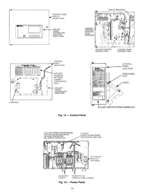
- Page 13: The PIC II can interface with the C
- Page 17 and 18: Start Chiller In CCN Control Start
- Page 19 and 20: SERVICE MENU CONTINUED FROM PREVIOU
- Page 21 and 22: 7. Press ENTER to register the valu
- Page 23 and 24: Table 2 — CVC/ICVC Display Data (
- Page 25 and 26: Table 2 — CVC/ICVC Display Data (
- Page 27 and 28: Table 2 — CVC/ICVC Display Data (
- Page 29 and 30: Table 2 — CVC/ICVC Display Data (
- Page 31 and 32: Table 2 — CVC/ICVC Display Data (
- Page 33 and 34: PIC II System Functions NOTE: Words
- Page 35 and 36: Shunt Trip (Option) — The functio
- Page 37 and 38: OVERRIDE CAPACITY CONTROL HIGH COND
- Page 39 and 40: (see wiring diagrams or certified d
- Page 41 and 42: NOTE: The lead/lag function can be
- Page 43 and 44: Ice Build Control — The ice build
- Page 45 and 46: Service Operation — An overview o
- Page 47 and 48: Shutdown Sequence — Chiller shutd
- Page 49 and 50: 49 Fig. 28 — 19XR Leak Test Proce
- Page 51 and 52: Fig. 29 — Typical Optional Pumpou
- Page 53 and 54: Chiller Dehydration — Dehydration
- Page 55 and 56: MECHANICAL STARTER 1. Check all fie
- Page 57 and 58: CHANGE THE BENSHAW INC., RediStart
- Page 59 and 60: VFD Cooling System Leak Inspection
- Page 61 and 62: Protecting the VFD Configuration 1.
- Page 63 and 64: Check Optional Pumpout System Contr
- Page 65 and 66:
Dry Run to Test Start-Up Sequence F
- Page 67 and 68:
Leave the oil charge in the chiller
- Page 69 and 70:
LEGEND C — Contactor FU — Fuse,
- Page 71 and 72:
2. Evacuate the refrigerant gas fro
- Page 73 and 74:
SCHEDULED MAINTENANCE Establish a r
- Page 75 and 76:
Water Treatment — Untreated or im
- Page 77 and 78:
TRANSDUCER REPLACEMENT — Since th
- Page 79 and 80:
Table 11 — CVC/ICVC Primary and S
- Page 81 and 82:
I. CHILLER PROTECT LIMIT FAULTS STA
- Page 83 and 84:
I. CHILLER PROTECT LIMIT FAULTS (co
- Page 85 and 86:
TEMPERATURE (F) PIC II VOLTAGE DROP
- Page 87 and 88:
Control Modules Turn controller pow
- Page 89 and 90:
ANALOG OUT J8 INTERGRATED STARTER M
- Page 91 and 92:
NOTES: 1. Cooler data: based on a c
- Page 93 and 94:
Table 14 — 19XR Additional Data f
- Page 95 and 96:
HEAT EXCHANGER COOLER/ CONDENSER HE
- Page 97 and 98:
Table 18 — Optional Pumpout Syste
- Page 99 and 100:
ITEM A B C D E F VIEW B — HIGH SP
- Page 101 and 102:
101 Fig. 45 — Allen-Bradley Wye-D
- Page 103 and 104:
103 LEGEND (cont) ISM — Integrate
- Page 105 and 106:
105 LEGEND (cont) ISM — Integrate
- Page 107 and 108:
107 LEGEND Denotes Component Termin
- Page 109 and 110:
AUX — Auxiliary C — Contactor C
- Page 111 and 112:
Fig. 53 — Benshaw, Inc. Solid-Sta
- Page 113 and 114:
LEGEND AUX — Auxiliary C — Cont
- Page 115 and 116:
1A LEGEND AUX — Auxiliary C — C
- Page 117 and 118:
117 Fig. 57 — Typical Variable Fr
- Page 119 and 120:
119 Fig. 57 — Typical Variable Fr
- Page 121 and 122:
121 Fig. 57 — Typical Variable Fr
- Page 123 and 124:
Abbreviations and Explanations, 4 A
- Page 125 and 126:
MACHINE INFORMATION: DESIGN CONDITI
- Page 127 and 128:
19XR, XRV PIC II SETPOINT TABLE CON
- Page 129 and 130:
CUT ALONG DOTTED LINE CUT ALONG DOT
- Page 131 and 132:
CUT ALONG DOTTED LINE CUT ALONG DOT
- Page 133 and 134:
CUT ALONG DOTTED LINE CUT ALONG DOT
- Page 135 and 136:
CUT ALONG DOTTED LINE CUT ALONG DOT
- Page 137 and 138:
CUT ALONG DOTTED LINE CUT ALONG DOT
- Page 140:
Copyright 2001 Carrier Corporation