

Start-Up, Operation, and Maintenance Instructions
Start-Up, Operation, and Maintenance Instructions
Start-Up, Operation, and Maintenance Instructions

Create successful ePaper yourself
Turn your PDF publications into a flip-book with our unique Google optimized e-Paper software.
OPTIONAL<br />
METER<br />
PACKAGE<br />
INTEGRATED<br />
STARTER<br />
MODULE<br />
(ISM)<br />
OIL PUMP<br />
DISCONNECT<br />
CONTROL<br />
AND OIL<br />
HEATER<br />
DISCONNECT<br />
COMPRESSOR<br />
MOTOR<br />
DISCONNECT<br />
General — The 19XR hermetic centrifugal liquid chiller<br />
contains a microprocessor-based control center that monitors<br />
<strong>and</strong> controls all operations of the chiller (see Fig. 9). The<br />
microprocessor control system matches the cooling capacity of<br />
the chiller to the cooling load while providing state-of-the-art<br />
chiller protection. The system controls cooling load within the<br />
set point plus the deadb<strong>and</strong> by sensing the leaving chilled water<br />
or brine temperature <strong>and</strong> regulating the inlet guide vane via a<br />
mechanically linked actuator motor. The guide vane is a variable<br />
flow pre-whirl assembly that controls the refrigeration effect<br />
in the cooler by regulating the amount of refrigerant vapor<br />
flow into the compressor. An increase in guide vane opening<br />
increases capacity. A decrease in guide vane opening decreases<br />
capacity. The microprocessor-based control center protects the<br />
chiller by monitoring the digital <strong>and</strong> analog inputs <strong>and</strong> executing<br />
capacity overrides or safety shutdowns, if required.<br />
AUTO Forward<br />
SPEED RUNNING MAN Reverse<br />
VOLTS REMOTE<br />
AMPS JOG PRO- RUN<br />
Hz<br />
AUTO GRAM JOB<br />
Kw<br />
FORWARD<br />
TORQUE REVERSE<br />
Password PROGRAM ENTER<br />
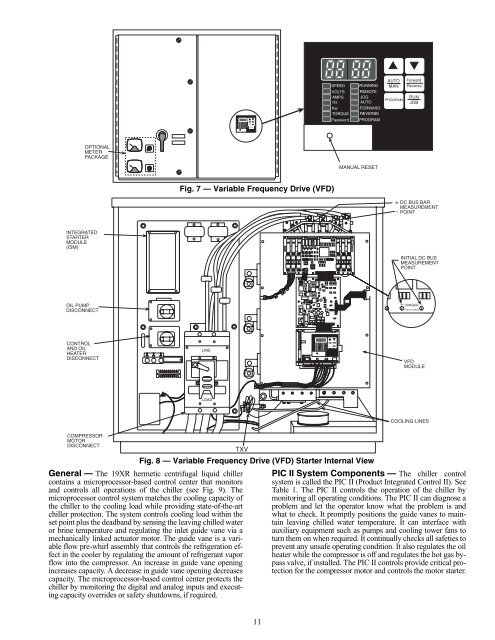
Fig. 7 — Variable Frequency Drive (VFD)<br />
LINE<br />
LOAD<br />
TXV<br />
11<br />
SPEED<br />
VOLTS<br />
AMPS<br />
Hz<br />
Kw<br />
TORQUE<br />
Password<br />
RUNNING MAN<br />
REMOTE<br />
PROGRAM<br />
JOG<br />
AUTO<br />
FORWARD<br />
REVERSE<br />
PROGRAM<br />
SPEED<br />
VOLTS<br />
AMPS<br />
Hz<br />
Kw<br />
TORQUE<br />
Password<br />
AUTO Forward<br />
Reverse<br />
RUN<br />
JOB<br />
ENTER<br />
AUTO<br />
RUNNING MAN<br />
REMOTE<br />
JOG<br />
PROGRAM<br />
AUTO<br />
FORWARD<br />
REVERSE<br />
PROGRAM<br />
MANUAL RESET<br />
Fig. 8 — Variable Frequency Drive (VFD) <strong>Start</strong>er Internal View<br />
ENTER<br />
Forward<br />
Reverse<br />
RUN<br />
JOB<br />
DC BUS BAR<br />
MEASUREMENT<br />
POINT<br />
INITIAL DC BUS<br />
MEASUREMENT<br />
POINT<br />
+ DANGER -<br />
HIGH VOLTAGE<br />
PIC II System Components — The chiller control<br />
system is called the PIC II (Product Integrated Control II). See<br />
Table 1. The PIC II controls the operation of the chiller by<br />
monitoring all operating conditions. The PIC II can diagnose a<br />
problem <strong>and</strong> let the operator know what the problem is <strong>and</strong><br />
what to check. It promptly positions the guide vanes to maintain<br />
leaving chilled water temperature. It can interface with<br />
auxiliary equipment such as pumps <strong>and</strong> cooling tower fans to<br />
turn them on when required. It continually checks all safeties to<br />
prevent any unsafe operating condition. It also regulates the oil<br />
heater while the compressor is off <strong>and</strong> regulates the hot gas bypass<br />
valve, if installed. The PIC II controls provide critical protection<br />
for the compressor motor <strong>and</strong> controls the motor starter.<br />
+<br />
-<br />
VFD<br />
MODULE<br />
COOLING LINES


