

Start-Up, Operation, and Maintenance Instructions
Start-Up, Operation, and Maintenance Instructions
Start-Up, Operation, and Maintenance Instructions

Create successful ePaper yourself
Turn your PDF publications into a flip-book with our unique Google optimized e-Paper software.
5. Using an ohmmeter, perform the following resistance<br />
measurements <strong>and</strong> record the results:<br />
MEASURE<br />
BETWEEN<br />
SCR PAIRS<br />
BEING<br />
CHECKED<br />
T1 <strong>and</strong> T6 3 <strong>and</strong> 6<br />
T2 <strong>and</strong> T4 2 <strong>and</strong> 5<br />
T3 <strong>and</strong> T5 1 <strong>and</strong> 4<br />
RECORDED<br />
VALUE<br />
If all measured values are greater than 5K ohms, proceed<br />
to Step 10. If any values are less than 5K ohms, one or<br />
more of the SCRs in that pair is shorted.<br />
6. Remove both SCRs in the pair (See SCR Removal/<br />
Installation).<br />
7. Using an ohmmeter, measure the resistance (anode to<br />
cathode) of each SCR to determine which device has<br />
failed.<br />
NOTE: Both SCRs may be defective, but typically, only<br />
one is shorted. If both SCRs provide acceptable resistance<br />
measurements, proceed to Step 10.<br />
8. Replace the defective SCR(s).<br />
9. Retest the “pair” for resistance values indicated above.<br />
10. On the right side of the firing card, measure the resistance<br />
between the red <strong>and</strong> white gate/cathode leads for each<br />
SCR (1 through 6). A measurement between 5 <strong>and</strong><br />
50 ohms is normal. Abnormally high values may indicate<br />
a failed gate for that SCR.<br />
If any red or white SCR gate leads are removed from the<br />
firing card or an SCR, care must be taken to ensure the<br />
leads are replaced EXACTLY as they were (white wires to<br />
gates, <strong>and</strong> red wires to cathodes on both the firing card <strong>and</strong><br />
SCR), or damage to the starter <strong>and</strong>/or motor may result.<br />
11. Replace the SCRs <strong>and</strong> retest the pair.<br />
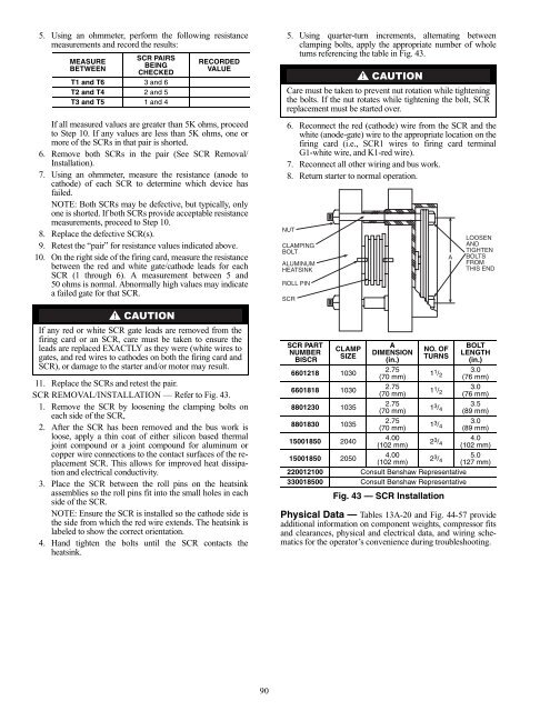
SCR REMOVAL/INSTALLATION — Refer to Fig. 43.<br />
1. Remove the SCR by loosening the clamping bolts on<br />
each side of the SCR,<br />
2. After the SCR has been removed <strong>and</strong> the bus work is<br />
loose, apply a thin coat of either silicon based thermal<br />
joint compound or a joint compound for aluminum or<br />
copper wire connections to the contact surfaces of the replacement<br />
SCR. This allows for improved heat dissipation<br />
<strong>and</strong> electrical conductivity.<br />
3. Place the SCR between the roll pins on the heatsink<br />
assemblies so the roll pins fit into the small holes in each<br />
side of the SCR.<br />
NOTE: Ensure the SCR is installed so the cathode side is<br />
the side from which the red wire extends. The heatsink is<br />
labeled to show the correct orientation.<br />
4. H<strong>and</strong> tighten the bolts until the SCR contacts the<br />
heatsink.<br />
90<br />
5. Using quarter-turn increments, alternating between<br />
clamping bolts, apply the appropriate number of whole<br />
turns referencing the table in Fig. 43.<br />
Care must be taken to prevent nut rotation while tightening<br />
the bolts. If the nut rotates while tightening the bolt, SCR<br />
replacement must be started over.<br />
6. Reconnect the red (cathode) wire from the SCR <strong>and</strong> the<br />
white (anode-gate) wire to the appropriate location on the<br />
firing card (i.e., SCR1 wires to firing card terminal<br />
G1-white wire, <strong>and</strong> K1-red wire).<br />
7. Reconnect all other wiring <strong>and</strong> bus work.<br />
8. Return starter to normal operation.<br />
NUT<br />
CLAMPING<br />
BOLT<br />
ALUMINUM<br />
HEATSINK<br />
ROLL PIN<br />
SCR<br />
SCR PART<br />
NUMBER<br />
BISCR<br />
CLAMP<br />
SIZE<br />
6601218 1030<br />
6601818 1030<br />
8801230 1035<br />
8801830 1035<br />
15001850 2040<br />
15001850 2050<br />
A<br />
DIMENSION<br />
(in.)<br />
2.75<br />
(70 mm)<br />
2.75<br />
(70 mm)<br />
2.75<br />
(70 mm)<br />
2.75<br />
(70 mm)<br />
4.00<br />
(102 mm)<br />
4.00<br />
(102 mm)<br />
NO. OF<br />
TURNS<br />
1 1 /2<br />
1 1/ 2<br />
1 3 /4<br />
1 3 /4<br />
2 3/ 4<br />
2 3 /4<br />
220012100 Consult Benshaw Representative<br />
330018500 Consult Benshaw Representative<br />
Fig. 43 — SCR Installation<br />
LOOSEN<br />
AND<br />
TIGHTEN<br />
BOLTS<br />
FROM<br />
THIS END<br />
BOLT<br />
LENGTH<br />
(in.)<br />
3.0<br />
(76 mm)<br />
3.0<br />
(76 mm)<br />
3.5<br />
(89 mm)<br />
3.0<br />
(89 mm)<br />
4.0<br />
(102 mm)<br />
5.0<br />
(127 mm)<br />
Physical Data — Tables 13A-20 <strong>and</strong> Fig. 44-57 provide<br />
additional information on component weights, compressor fits<br />
<strong>and</strong> clearances, physical <strong>and</strong> electrical data, <strong>and</strong> wiring schematics<br />
for the operator’s convenience during troubleshooting.<br />
A


