

Start-Up, Operation, and Maintenance Instructions
Start-Up, Operation, and Maintenance Instructions
Start-Up, Operation, and Maintenance Instructions

Create successful ePaper yourself
Turn your PDF publications into a flip-book with our unique Google optimized e-Paper software.
Protecting the VFD Configuration<br />
1. Select parameter P.051 from the VFD keypad.<br />
2. Press the ENTER softkey to access the parameter. A<br />
zero will be displayed.<br />
3. Use the ↑ arrow key to increment the value to 26. This is<br />
the password number.<br />
4. Press the ENTER softkey to save the value. P.051 will<br />
by displayed.<br />
NOTE: Parameter programming is disabled when the<br />
PASSWORD LED is on <strong>and</strong> enabled when the PASS-<br />
WORD LED is off.<br />
5. Select parameter P.006 from the VFD Keypad.<br />
6. Press the ENTER softkey to access the parameter.<br />
7. Use the ↑ arrow key to increment the value to 107. This<br />
is the password number to restrict displaying the remaining<br />
P, <strong>and</strong> all of the H <strong>and</strong> r parameters.<br />
8. Press the ENTER softkey to save the value.<br />
Modify Minimum <strong>and</strong> Maximum Load Points (∆T1/P1; ∆T2/<br />
P2) If Necessary — These pairs of chiller load points, located<br />
on the OPTIONS screen, determine when to limit guide vane<br />
travel or open the hot gas bypass valve when surge prevention<br />
is needed. These points should be set based on individual<br />
chiller operating conditions.<br />
A label that lists the configuration values of the controls is<br />
located on the inside of the unit’s control panel. These values<br />
are based upon the original selection of the chiller. Jobsite conditions<br />
may require a slight modification to these parameters.<br />
If after configuring a value for these points, surge prevention<br />
is operating too soon or too late for conditions, these parameters<br />
should be changed by the operator.<br />
An example of such a configuration is shown below.<br />
Refrigerant: HCFC-134a<br />
Estimated Minimum Load Conditions:<br />
44 F (6.7 C) LCW<br />
45.5 F (7.5 C) ECW<br />
43 F (6.1 C) Suction Temperature<br />
70 F (21.1 C) Condensing Temperature<br />
Estimated Maximum Load Conditions:<br />
44 F (6.7 C) LCW<br />
54 F (12.2 C) ECW<br />
42 F (5.6 C) Suction Temperature<br />
98 F (36.7 C) Condensing Temperature<br />
Calculate Maximum Load — To calculate the maximum load<br />
points, use the design load condition data. If the chiller full load<br />
cooler temperature difference is more than 15 F (8.3 C), estimate<br />
the refrigerant suction <strong>and</strong> condensing temperatures at<br />
this difference. Use the proper saturated pressure <strong>and</strong> temperature<br />
for the particular refrigerant used.<br />
Suction Temperature:<br />
42 F (5.6 C) = 37 psig (255 kPa) saturated<br />
refrigerant pressure (HFC-134a)<br />
Condensing Temperature:<br />
98 F (36.7 C) = 120 psig (1827 kPa) saturated<br />
refrigerant pressure (HFC-134a)<br />
Maximum Load ∆T2:<br />
54 – 44 = 10º F (12.2 – 6.7 = 5.5º C)<br />
Maximum Load ∆P2:<br />
120 – 37 = 83 psid (827 – 255 = 572 kPad)<br />
To avoid unnecessary surge prevention, add about 10 psid<br />
(70 kPad) to ∆P2 from these conditions:<br />
∆T2 = 10º F (5.5º C)<br />
∆P2 = 93 psid (642 kPad)<br />
61<br />
Calculate Minimum Load — To calculate the minimum load<br />
conditions, estimate the temperature difference the cooler will<br />
have at 10% load, then estimate what the suction <strong>and</strong> condensing<br />
temperatures will be at this point. Use the proper saturated<br />
pressure <strong>and</strong> temperature for the particular refrigerant used.<br />
Suction Temperature:<br />
43 F (6.1 C) = 38 psig (262 kPa) saturated<br />
refrigerant pressure (HFC-134a)<br />
Condensing Temperature:<br />
70 F (21.1 C) = 71 psig (490 kPa) saturated<br />
refrigerant pressure (HFC-134a)<br />
Minimum Load ∆T1 (at 20% Load): 2 F (1.1 C)<br />
Minimum Load ∆P1:<br />
71 – 38 = 33 psid (490 – 262 = 228 kPad)<br />
Again, to avoid unnecessary surge prevention, add 20 psid<br />
(140 kPad) at ∆P1 from these conditions:<br />
∆T1 = 2 F (1.1 C)<br />
∆P1 = 53 psid (368 kPad)<br />
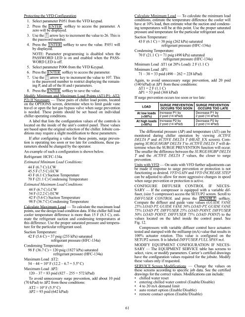
If surge prevention occurs too soon or too late:<br />
LOAD<br />
At low loads<br />
(50%)<br />
SURGE PREVENTION SURGE PREVENTION<br />
OCCURS TOO SOON OCCURS TOO LATE<br />
Increase P1 by Decrease P1 by<br />
2 psid (14 kPad) 2 psid (14 kPad)<br />
Increase P2 by<br />
2 psid (14 kPad)<br />
Decrease P2 by<br />
2 psid (14 kPad)<br />
The differential pressure (∆P) <strong>and</strong> temperature (∆T) can be<br />
monitored during chiller operation by viewing ACTIVE<br />
DELTA P <strong>and</strong> ACTIVE DELTA T (HEAT_EX screen). Comparing<br />
SURGE/HGBP DELTA T to ACTIVE DELTA T will determine<br />
when the SURGE PREVENTION function will occur.<br />
The smaller the difference between the SURGE/HGBP DELTA<br />
T <strong>and</strong> the ACTIVE DELTA T values, the closer to surge<br />
prevention.<br />
Units with VFD — On units with VFD further adjustments can<br />
be made if response to surge prevention or protection is not<br />
functioning as desired. VFD GAIN <strong>and</strong> VFD INCREASE STEP<br />
can be adjusted to allow for more aggressive changes in speed<br />
when surge prevention or protection is active.<br />
CONFIGURE DIFFUSER CONTROL IF NECES-<br />
SARY — If the compressor is equipped with a variable diffuser,<br />
(size 5 compressor) access the SETUP2 screen. Scroll to<br />
DIFFUSER CONTROL <strong>and</strong> press the ENABLE<br />
softkey.<br />
Compare the diffuser <strong>and</strong> guide vane values (GUIDE VANE<br />
25% LOAD PT, GUIDE VANE 50% LOAD PT, GUIDE VANE<br />
75% LOAD PT, DIFFUSER 25% LOAD POINT, DIFFUSER<br />
50% LOAD POINT, DIFFUSER 75% LOAD POINT) to the<br />
values located on the label inside the control panel. See<br />
Fig. 12.<br />
Compressors with variable diffuser control have actuators<br />
tested <strong>and</strong> stamped with the milliamp (mA) value that results in<br />
100% actuator rotation. This value is configured on the<br />
SETUP2 screen. It is labeled DIFFUSER FULL SPAN mA.<br />
MODIFY EQUIPMENT CONFIGURATION IF NECES-<br />
SARY — The EQUIPMENT SERVICE table has screens to<br />
select, view, or modify parameters. Carrier’s certified drawings<br />
have the configuration values required for the jobsite. Modify<br />
these values only if requested.<br />
SERVICE Screen Modifications — Change the values on<br />
these screens according to specific job data. See the certified<br />
drawings for the correct values. Modifications can include:<br />
chilled water reset<br />
entering chilled water control (Enable/Disable)<br />
4 to 20 mA dem<strong>and</strong> limit<br />
auto restart option (Enable/Disable)<br />
remote contact option (Enable/Disable)


