

User's Manual TNC 360 (from 259 900-11) - heidenhain
User's Manual TNC 360 (from 259 900-11) - heidenhain
User's Manual TNC 360 (from 259 900-11) - heidenhain

Create successful ePaper yourself
Turn your PDF publications into a flip-book with our unique Google optimized e-Paper software.
7 Programming with Q Parameters<br />
7.1 Q Parameters Instead of Numerical Values<br />
7-4<br />
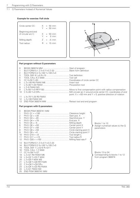
Example for exercise: Full circle<br />
Circle center CC: X = 50 mm<br />
Beginning and end<br />
Y = 50 mm<br />
of circular arc C: X = 50 mm<br />
Y = 0 mm<br />
Milling depth: Z = –5 mm<br />
Tool radius: R = 15 mm<br />
Part program without Q parameters<br />
0 BEGIN <strong>360</strong>074 MM ............................................ Start of program<br />
1 BLK FORM 0.1 Z X+0 Y+0 Z–20 ........................ Blank form definition<br />
2 BLK FORM 0.2 X+100 Y+100 Z+0<br />
3 TOOL DEF 6 L+0 R+15 ...................................... Tool definition<br />
4 TOOL CALL 6 Z S500 ......................................... Tool call<br />
5 CC X+50 Y+50 .................................................... Coordinates of circle center CC<br />
6 L Z+100 R0 FMAX M6 ....................................... Insert tool<br />
7 L X+30 Y–20 FMAX ............................................ Pre-position tool<br />
8 L Z–5 FMAX M3<br />
9 L X+50 Y+0 RR F100 .......................................... Move to first compensation point with radius compensation<br />
10 C X+50 Y+0 DR+ ................................................ Mill circular arc C around circle center CC; coordinates of end<br />
point: X = +50 mm and Y = 0; positive direction of rotation<br />
<strong>11</strong> L X+70 Y–20 R0 FMAX<br />
12 L Z+100 FMAX M2<br />
13 END PGM <strong>360</strong>074 MM ...................................... Retract tool and end program<br />
Part program with Q parameters<br />
0 BEGIN PGM <strong>360</strong>0741 MM<br />
1 FN 0: Q1 = +100 ................................................ Clearance height<br />
2 FN 0: Q2 = +30 .................................................. Start pos. X<br />
3 FN 0: Q3 = –20 ................................................... Start-End pos. Y<br />
4 FN 0: Q4 = +70 .................................................. End pos. X<br />
5 FN 0: Q5 = –5 ..................................................... Milling depth<br />
6 FN 0: Q6 = +50 .................................................. Center point X<br />
7 FN 0: Q7 = +50 .................................................. Center point Y<br />
8 FN 0: Q8 = +50 .................................................. Circle starting point X<br />
9 FN 0: Q9 = +0 .................................................... Circle starting point Y<br />
10 FN 0: Q10 = +0 .................................................. Tool length L<br />
<strong>11</strong> FN 0: Q<strong>11</strong> = +15 ................................................ Tool radius R<br />
12 FN 0: Q20 = +100 .............................................. Milling feed rate F<br />
13 BLK FORM 0.1.Z X+0 Y+0 Z–20<br />
14 BLK FORM 0.2 X+100 Y+100 Z+0<br />
15 TOOL DEF 1 L+Q10 R+Q<strong>11</strong><br />
16 TOOL CALL 1 Z S500<br />
17 CC X+Q6 Y+Q7<br />
18 L Z+Q1 R0 FMAX M6<br />
19 L X+Q2 Y+Q3 F MAX<br />
20 L Z+Q5 F MAX M3<br />
21 L X+Q8 Y+Q9 RR FQ20<br />
22 C X+Q8 Y+Q9 DR+<br />
23 L X+Q4 Y+Q3 R0 FMAX<br />
24 L Z+Q1 FMAX M2<br />
25 END PGM <strong>360</strong>0741 MM<br />
Y<br />
50<br />
–5<br />
Z<br />
CC<br />
50<br />
Blocks 1 to 12:<br />
Assign numerical values to the Q<br />
parameters<br />
Blocks 13 to 24:<br />
Corresponding to blocks 1 to 12<br />
<strong>from</strong> program <strong>360</strong>074<br />
X<br />
<strong>TNC</strong> <strong>360</strong>


