

User's Manual TNC 360 (from 259 900-11) - heidenhain
User's Manual TNC 360 (from 259 900-11) - heidenhain
User's Manual TNC 360 (from 259 900-11) - heidenhain

You also want an ePaper? Increase the reach of your titles
YUMPU automatically turns print PDFs into web optimized ePapers that Google loves.
8 Cycles<br />
8.3 SL Cycles<br />
<strong>TNC</strong> <strong>360</strong><br />
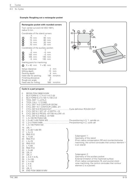
Example: Roughing out a rectangular pocket<br />
Rectangular pocket with rounded corners<br />
Tool: center-cut end mill (ISO 1641),<br />
radius 5 mm.<br />
Coordinates of the island corners:<br />
X Y<br />
1 70 mm 60 mm<br />
2 15 mm 60 mm<br />
3 15 mm 20 mm<br />
4 70 mm 20 mm<br />
Coordinates of the auxiliary pocket:<br />
X Y<br />
6 –5 mm –5 mm<br />
7 105 mm –5 mm<br />
8 105 mm 105 mm<br />
9 –5 mm 105 mm<br />
Starting point for machining:<br />
5 X = 40 mm Y = 60 mm<br />
Setup clearance: 2 mm<br />
Milling depth: 15 mm<br />
Pecking depth: 8 mm<br />
Feed rate for pecking: 100 mm/min<br />
Finishing allowance: 0<br />
Rough-out angle: 00 Feed rate for milling: 500 mm/min<br />
Cycle in a part program<br />
Y<br />
60<br />
20<br />
2<br />
5<br />
3 4<br />
15 70<br />
R12<br />
1<br />
LBL<br />
0 BEGIN PGM <strong>360</strong>819 MM<br />
1 BLK FORM 0.1 Z X+0 Y+0 Z–20<br />
2 BLK FORM 0.2 X+100 Y+100 Z+0<br />
3 TOOL DEF 1 L+0 R+3<br />
4 TOOL CALL 1 Z S1000<br />
5 CYCL DEF 14.0 CONTOUR GEOM.<br />
6 CYCL DEF 14.1 CONTOUR LABEL 2/1<br />
7 CYCL DEF 6.0 ROUGH-OUT .............................. Cycle definition ROUGH-OUT<br />
8 CYCL DEF 6.1 SET UP –2 DEPTH –15<br />
9 CYCL DEF 6.2 PECKG –8 F100 ALLOW +0<br />
10 CYCL DEF 6.3 ANGLE +0 F500<br />
<strong>11</strong> L Z+100 R0 FMAX M6<br />
12 L X+40 Y+50 FMAX M3 ..................................... Pre-positioning in X, Y, spindle on<br />
13 L Z+2 FMAX M99 ............................................... Pre-positioning in Z, cycle call<br />
14 L Z+100 FMAX M2<br />
15 LBL 1<br />
16 L X+40 Y+60 RR<br />
17 L X+15<br />
18 RND R12<br />
19 L Y+20<br />
20 RND R12<br />
21 L X+70<br />
22 RND R12<br />
23 L Y+60<br />
24 RND R12<br />
25 L X+40<br />
26 LBL 0<br />
27 LBL 2<br />
28 L X–5 Y–5 RL<br />
29 L X+105<br />
30 L Y+105<br />
31 L X–5<br />
32 L Y–5<br />
33 LBL 0<br />
34 END PGM <strong>360</strong>819 MM<br />
9<br />
X<br />
6<br />
Subprogram 1:<br />
Geometry of the island<br />
(From radius compensation RR and counterclockwise<br />
machining, the control concludes that contour element 1<br />
is an island)<br />
Subprogram 2:<br />
Geometry of the auxiliary pocket<br />
External limitation of the machined surface<br />
(From radius compensation RL and counter-clockwise<br />
machining, the control concludes that contour<br />
element 2 is a pocket)<br />
8<br />
7<br />
8-19


