

User's Manual TNC 360 (from 259 900-11) - heidenhain
User's Manual TNC 360 (from 259 900-11) - heidenhain
User's Manual TNC 360 (from 259 900-11) - heidenhain

You also want an ePaper? Increase the reach of your titles
YUMPU automatically turns print PDFs into web optimized ePapers that Google loves.
9 Digitizing 3D Surfaces<br />
9.4 Contour Line Digitizing<br />
<strong>TNC</strong> <strong>360</strong><br />
The <strong>TNC</strong> generates an NC part program <strong>from</strong> the digitized data. The<br />
program name is entered in the scanning cycle RANGE.<br />
During machine execution, the tool radius determines the shape of the<br />
machined contour.<br />
When tool radius equals the effective probe tip radius<br />
The program can be run without any changes. The model that has been<br />
scanned is reproduced.<br />
When the tool radius does not equal the effective probe tip radius<br />
In this case the machined part will be either smaller or larger than the<br />
model. The HEIDENHAIN evaluation software SUSA can reproduce the<br />
original shape of workpiece models that were scanned with the meander<br />
scanning process.<br />
9.5 Using Digitized Data in a Part Program<br />
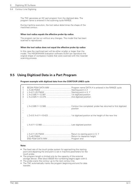
Program example with digitized data <strong>from</strong> the CONTOUR LINES cycle<br />
0 BEGIN PGM DATA MM ..................................... Program name DATA.H is entered in the RANGE cycle<br />
1 L Z+40 FMAX ..................................................... Starting point in Z<br />
2 L X+0 Y–25 FMAX .............................................. Starting point in X, Y<br />
3 L X+2.005 Y–12.561 ........................................... 1st digitized position<br />
4 L X+2.025 Y–12.375 ........................................... 2nd digitized position<br />
.<br />
.<br />
.<br />
.<br />
.<br />
.<br />
.<br />
.<br />
.<br />
.<br />
.<br />
.<br />
L X+2.005 Y–12.560 ........................................... Contour line completed: probe has returned to first digitized<br />
position<br />
L Z+0.5 X+0 Y–10.423 ........................................ 1st digitized position at the height of the new line<br />
L X+0 Y–12.560 .................................................. Last digitized position<br />
L X+0 Y–25 FMAX .............................................. Return to starting point in X, Y<br />
L Z+40 FMAX ..................................................... Return to clearance height<br />
END PGM DATA MM ......................................... Program end<br />
Note:<br />
• The feed rate of the touch probe system for approaching the starting<br />
point and departing the end point is set in machine parameters for the<br />
touch probe.<br />
• The program length is limited only by the capacity of the external<br />
storage device. After block 65535 the numbering begins again with 0.<br />
• The probe scans the contour up to the next contour line.<br />
• The <strong>TNC</strong> automatically marks the program beginning and end for data<br />
transfer.<br />
9-<strong>11</strong>


