

User's Manual TNC 360 (from 259 900-11) - heidenhain
User's Manual TNC 360 (from 259 900-11) - heidenhain
User's Manual TNC 360 (from 259 900-11) - heidenhain

You also want an ePaper? Increase the reach of your titles
YUMPU automatically turns print PDFs into web optimized ePapers that Google loves.
8 Cycles<br />
8.2 Simple Fixed Cycles<br />
POCKET MILLING (Cycle 4)<br />
8-12<br />
Process<br />
The rectangular pocket milling cycle is a roughing cycle, in which<br />
• the tool penetrates the workpiece at the starting position (pocket<br />
center)<br />
• the tool subsequently follows the programmed path at the specified<br />
feed rate (see Fig. 8.9) .<br />
The cutter begins milling in the positive axis direction of the longer side.<br />
With square pockets, the cutter begins in the positive Y-direction. At the<br />
end of the cycle, the tool returns to the starting position.<br />
Requirements / Limitations<br />
This cycle requires a center-cut end mill (ISO 1641) or a separate pilot<br />
drilling operation at the pocket center. The pocket sides are parallel to the<br />
axes of the coordinate system.<br />
Input data<br />
• Setup clearance A<br />
• Milling depth B<br />
• Pecking depth C<br />
• FEED RATE FOR PECKING:<br />
Traversing speed of the tool during penetration.<br />
• FIRST SIDE LENGTH D :<br />
Length of the pocket, parallel to the first main axis of the working<br />
plane.<br />
• SECOND SIDE LENGTH E :<br />
Width of the pocket<br />
The signs of the side lengths are always positive<br />
• FEED RATE:<br />
Traversing speed of the tool in the working plane.<br />
• DIRECTION OF THE MILLING PATH:<br />
DR + : Climb milling with M3<br />
DR – : Up-cut milling with M3<br />
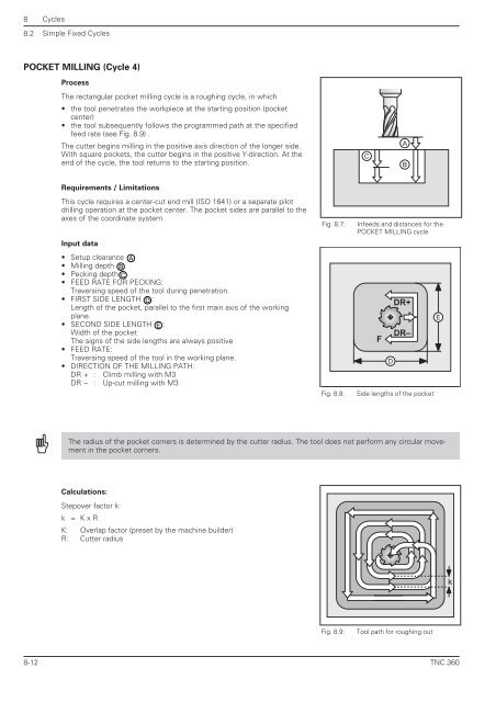
Fig. 8.7: Infeeds and distances for the<br />
POCKET MILLING cycle<br />
Fig. 8.8: Side lengths of the pocket<br />
The radius of the pocket corners is determined by the cutter radius. The tool does not perform any circular movement<br />
in the pocket corners.<br />
Calculations:<br />
Stepover factor k:<br />
k = K x R<br />
K: Overlap factor (preset by the machine builder)<br />
R: Cutter radius<br />
C<br />
F<br />
Fig. 8.9: Tool path for roughing out<br />
D<br />
A<br />
B<br />
DR+<br />
DR–<br />
E<br />
k<br />
<strong>TNC</strong> <strong>360</strong>


