- Page 1 and 2: May 1994 HEIDENHAIN User's Manual H
- Page 3 and 4: TNC Guideline: From workpiece drawi
- Page 5 and 6: How to use this manual TNC 360 This
- Page 7 and 8: Contents User's Manual TNC 360 (fro
- Page 9 and 10: 2 Manual Operation and Setup TNC 36
- Page 11 and 12: 4 Programming TNC 360 4.1 Editing p
- Page 13 and 14: 6 Subprograms and Program Section R
- Page 15 and 16: 8 Cycles TNC 360 8.1 General Overvi
- Page 17 and 18: 10 External Data Transfer TNC 360 1
- Page 19 and 20: 12 Tables, Overviews, Diagrams TNC
- Page 21 and 22: 1 Introduction 1.1 The TNC 360 The
- Page 23 and 24: 1 Introduction 1.1 The TNC 360 TNC
- Page 25 and 26: 1 Introduction 1.2 Fundamentals of
- Page 27 and 28: 1 Introduction 1.2 Fundamentals of
- Page 29 and 30: 1 Introduction 1.2 Fundamentals of
- Page 31: 1 Introduction Programming tool mov
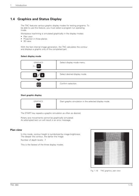
- Page 35 and 36: 1 Introduction 1.4 Graphics and Sta
- Page 37 and 38: 1 Introduction 1.5 Programs The TNC
- Page 39 and 40: 1 Introduction 1.5 Programs To remo
- Page 41 and 42: 2 Manual Operation and Setup Traves
- Page 43 and 44: 2 Manual Operation and Setup 2.2 Sp
- Page 45 and 46: 2 Manual Operation and Setup 2.3 Se
- Page 47 and 48: 2 Manual Operation and Setup 2.4 3D
- Page 49 and 50: 2 Manual Operation and Setup 2.4 3D
- Page 51 and 52: 2 Manual Operation and Setup 2.4 3D
- Page 53 and 54: 2 Manual Operation and Setup 2.5 Se
- Page 55 and 56: 2 Manual Operation and Setup 2.5 Se
- Page 57 and 58: 2 Manual Operation and Setup 2.6 Me
- Page 59 and 60: 2 Manual Operation and Setup 2.6 Me
- Page 61 and 62: 3 Test Run and Program Run 3.1 Test
- Page 63 and 64: 3 Test Run and Program Run 3.2 Prog
- Page 65 and 66: 3 Test Run and Program Run 3.3 Bloc
- Page 67 and 68: 4 Programming 4-2 In the PROGRAMMIN
- Page 69 and 70: 4 Programming 4.1 Editing Part Prog
- Page 71 and 72: 4 Programming 4.2 Tools 4-6 Determi
- Page 73 and 74: 4 Programming 4.2 Tools Entering to
- Page 75 and 76: 4 Programming 4.2 Tools Tool change
- Page 77 and 78: 4 Programming 4.3 Tool Compensation
- Page 79 and 80: 4 Programming 4.3 Tool Compensation
- Page 81 and 82: 4 Programming 4.5 Entering Tool-Rel
- Page 83 and 84:
4 Programming 4.6 Entering Miscella
- Page 85 and 86:
4 Programming 4-20 Generating a new
- Page 87 and 88:
5 Programming Tool Movements 5.1 Ge
- Page 89 and 90:
5 Programming Tool Movements 5.2 Co
- Page 91 and 92:
5 Programming Tool Movements 5.3 Pa
- Page 93 and 94:
5 Programming Tool Movements 5.4 Pa
- Page 95 and 96:
5 Programming Tool Movements 5.4 Pa
- Page 97 and 98:
5 Programming Tool Movements 5.4 Pa
- Page 99 and 100:
5 Programming Tool Movements 5.4 Pa
- Page 101 and 102:
5 Programming Tool Movements 5.4 Pa
- Page 103 and 104:
5 Programming Tool Movements 5.4 Pa
- Page 105 and 106:
5 Programming Tool Movements 5.4 Pa
- Page 107 and 108:
5 Programming Tool Movements 5.4 Pa
- Page 109 and 110:
5 Programming Tool Movements 5.4 Pa
- Page 111 and 112:
5 Programming Tool Movements 5.5 Pa
- Page 113 and 114:
5 Programming Tool Movements 5.5 Pa
- Page 115 and 116:
5 Programming Tool Movements 5.5 Pa
- Page 117 and 118:
5 Programming Tool Movements 5.5 Pa
- Page 119 and 120:
5 Programming Tool Movements 5.5 Pa
- Page 121 and 122:
5 Programming Tool Movements 5.6 M-
- Page 123 and 124:
5 Programming Tool Movements 5.6 M-
- Page 125 and 126:
6 Subprograms and Program Section R
- Page 127 and 128:
6 Subprograms and Program Section R
- Page 129 and 130:
6 Subprograms and Program Section R
- Page 131 and 132:
6 Subprograms and Program Section R
- Page 133 and 134:
6 Subprograms and Program Section R
- Page 135 and 136:
6 Subprograms and Program Section R
- Page 137 and 138:
7 Programming with Q Parameters 7.1
- Page 139 and 140:
7 Programming with Q Parameters 7.2
- Page 141 and 142:
7 Programming with Q Parameters 7.3
- Page 143 and 144:
7 Programming with Q Parameters 7.4
- Page 145 and 146:
7 Programming with Q Parameters 7.6
- Page 147 and 148:
7 Programming with Q Parameters 7.7
- Page 149 and 150:
7 Programming with Q Parameters 7.8
- Page 151 and 152:
7 Programming with Q Parameters 7.8
- Page 153 and 154:
7 Programming with Q Parameters 7.8
- Page 155 and 156:
8 Cycles 8.1 General Overview of Cy
- Page 157 and 158:
8 Cycles 8.1 General Overview Dimen
- Page 159 and 160:
8 Cycles 8.2 Simple Fixed Cycles 8-
- Page 161 and 162:
8 Cycles 8.2 Simple Fixed Cycles 8-
- Page 163 and 164:
8 Cycles 8.2 Simple Fixed Cycles SL
- Page 165 and 166:
8 Cycles 8.2 Simple Fixed Cycles PO
- Page 167 and 168:
8 Cycles 8.2 Simple Fixed Cycles CI
- Page 169 and 170:
8 Cycles 8.3 SL Cycles 8-16 Subcont
- Page 171 and 172:
8 Cycles 8.3 SL Cycles ROUGH-OUT (C
- Page 173 and 174:
8 Cycles 8.3 SL Cycles SL Cycles: O
- Page 175 and 176:
8 Cycles 8.3 SL Cycles 8-22 Area of
- Page 177 and 178:
8 Cycles 8.3 SL Cycles 8-24 Area of
- Page 179 and 180:
8 Cycles 8.3 SL Cycles PILOT DRILLI
- Page 181 and 182:
8 Cycles 8.3 SL Cycles 8-28 The fol
- Page 183 and 184:
8 Cycles 8.4 Cycles for Coordinate
- Page 185 and 186:
8 Cycles 8.4 Cycles for Coordinate
- Page 187 and 188:
8 Cycles 8.4 Cycles for Coordinate
- Page 189 and 190:
8 Cycles 8.4 Cycles for Coordinate
- Page 191 and 192:
8 Cycles 8.5 Other Cycles DWELL TIM
- Page 193 and 194:
9 Digitizing 3D Surfaces 9-2 The di
- Page 195 and 196:
9 Digitizing 3D Surfaces 9.2 Digiti
- Page 197 and 198:
9 Digitizing 3D Surfaces 9.3 Line-B
- Page 199 and 200:
9 Digitizing 3D Surfaces 9.4 Contou
- Page 201 and 202:
9 Digitizing 3D Surfaces 9.4 Contou
- Page 203 and 204:
9 Digitizing 3D Surfaces 9.5 Using
- Page 205 and 206:
10 External Data Transfer 10.2 Pin
- Page 207 and 208:
11 MOD Functions 11-2 The MOD funct
- Page 209 and 210:
11 MOD Functions 11.5 Machine-Speci
- Page 211 and 212:
11 MOD Functions 11.10 Setting the
- Page 213 and 214:
12 Tables, Overviews, Diagrams 12.1
- Page 215 and 216:
12 Tables, Overviews, Diagrams 12.1
- Page 217 and 218:
12 Tables, Overviews, Diagrams 12.1
- Page 219 and 220:
12 Tables, Overviews, Diagrams 12.1
- Page 221 and 222:
12 Tables, Overviews, Diagrams 12.2
- Page 223 and 224:
12 Tables, Overviews, Diagrams 12.3
- Page 225 and 226:
12 Tables, Overviews, Diagrams 12.4
- Page 227 and 228:
12 Tables, Overviews, Diagrams 12.4
- Page 229 and 230:
12 Tables, Overviews, Diagrams 12.5
- Page 231 and 232:
12 Tables, Overviews, Diagrams 12.6
- Page 233 and 234:
12 Tables, Overviews, Diagrams 12.6
- Page 235 and 236:
12 Tables, Overviews, Diagrams 12.6
- Page 237:
Miscellaneous Functions (M Function


