

Repair Kits Available By Part Number Section 2 Page - GAMECO
Repair Kits Available By Part Number Section 2 Page - GAMECO
Repair Kits Available By Part Number Section 2 Page - GAMECO

You also want an ePaper? Increase the reach of your titles
YUMPU automatically turns print PDFs into web optimized ePapers that Google loves.
WARNING: Installation, disassembly, repair and maintenance must<br />
be performed only by qualified personnel.<br />
All gas MUST be isolated from the system before starting repairs.<br />
Maintenance may be performed with the valve installed or with<br />
valve removed from the line. In either case, the gas supply must be<br />
isolated from the line by closing a separate shut-off valve.<br />
Installation, usage and maintenance of this product must be in<br />
compliance with all Engineered Controls International, Inc. instructions<br />
as well as requirements and provisions of NFPA #54, NFPA<br />
#58, DOT, ANSI, all applicable federal, state provincial and local<br />
standards, codes, regulations and laws.<br />
Inspection and maintenance on a periodic basis is essential.<br />
Be sure all instructions are read and understood before installation,<br />
operation and maintenance. These instructions must be<br />
passed along to the end user of the product.<br />
CAUTION: Contact or inhalation of liquid propane, ammonia and<br />
their vapors can cause serious injury or death! NH 3<br />
and LP-Gas<br />
must be released outdoors in air currents that will insure dispersion<br />
to prevent exposure to people and livestock. LP-Gas must be kept<br />
far enough from any open flame or other source of ignition to<br />
prevent fire or explosion! LP-Gas is heavier than air and may not<br />
disperse or evaporate rapidly if released in still air.<br />
Disassembly and <strong>Repair</strong> Procedure<br />
CAUTION: READ THROUGH ALL OF THESE INSTRUCTIONS, IN-<br />
CLUDING THE NOTICE AND WARNINGS ON THE BACK OF THIS<br />
SHEET, BEFORE BEGINNING ANY DISASSEMBLY OR REPAIR.<br />
NOTE: <strong>Repair</strong>s must be performed in a clean area. Hands, clothing,<br />
tools and work area must be completely free of oil, grease and foreign<br />
matter to prevent contamination of component parts and valves.<br />
A. Disassembly<br />
1. EVACUATE ALL GAS FROM THE SYSTEM BEFORE ANY DISAS-<br />
SEMBLY OR REPAIR. Open handwheel as far as it will go to release<br />
any gas remaining in the system.<br />
CAUTION: Do not apply force after valve is fully open.<br />
2. Using a 3 /4" wrench, remove the four cap screws from bonnet by<br />
turning counterclockwise, lift bonnet away from valve body.<br />
3. Remove body gasket and discard.<br />
TO INSTALL NEW SEAT DISC:<br />
4. Clamp the square section of bonnet in a vise.<br />
TA7511A-50 Assembly for<br />
TA7511AP, TA7511FP, TA7512AP<br />
& TA7512FP Shut-Off Valves<br />
5. While holding the hex section of the seat disc retainer with a wrench,<br />
use another wrench to remove the disc retaining nut. Save for<br />
reassembly.<br />
6. Remove and discard seat disc.<br />
7. Soak new seat disc (A7511F-4T) in water prior to installation.<br />
8. Press seat disc into recess of seat disc retainer as shown in Figure<br />
2.<br />
9. Apply Loctite cement (5555LT) to the first three threads of seat disc<br />
retainer.<br />
CAUTION: Do not allow Loctite to contact seat disc.<br />
10. Thread on disc retaining nut and tighten with a wrench to<br />
150-175 in/lbs torque.<br />
11. Stake nut in two places at retainer threads to prevent loosening (see<br />
Figure 2).<br />
NOTE: If no further repairs are required, disregard steps A-12 through<br />
A-17 and B-1 through B-9 of the instructions. Finish reassembly by<br />
following steps B-10 through B-14 only. TO INSTALL ALL OF THE<br />
TA7511A-50 REPAIR PARTS, FOLLOW ALL OF THE REMAINING<br />
INSTRUCTIONS.<br />
12. Remove handwheel locknut by turning counterclockwise with a<br />
small wrench to allow removal of washer, information disc and<br />
handwheel.<br />
13. Using a 1 5 /16" wrench with a handle of sufficient length to develop<br />
a minimum of 1000 in/lbs torque, turn seat housing counterclockwise<br />
and carefully remove from bonnet.<br />
CAUTION: Do not mar finish of stem.<br />
14. Remove and discard pressure seal rings and O-ring from seal<br />
housing.<br />
15. Using a small wrench on the square section, screw stem down and<br />
out through the bottom of bonnet by turning clockwise (as viewed<br />
from top).<br />
CAUTION: If stem is scratched or scored, a new one must be<br />
installed.<br />
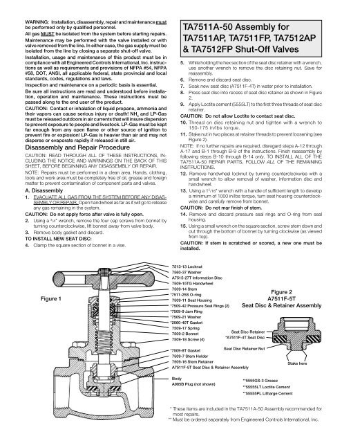
Figure 1<br />
7513-13 Locknut<br />
7560-37 Washer<br />
A7515-27T Information Disc<br />
7509-15TG Handwheel<br />
7509-14 Stem<br />
*7511-25S O-ring<br />
7509-11 Seat Housing<br />
*7509-42 Pressure Seal Rings (2)<br />
*7509-9 Jam Ring<br />
*7509-21 Washer<br />
*2060-40T Gasket<br />
7509-17 Spring<br />
7509-2 Bonnet<br />
7509-18 Screw (4)<br />
Figure 2<br />
A7511F-5T<br />
Seat Disc & Retainer Assembly<br />
Seat Disc Retainer<br />
*A7511F-4T Seat Disc<br />
*7509-8T Gasket<br />
Seat Disc Retainer Nut<br />
7509-7 Stem Holder<br />
7509-16 Stem Retainer<br />
A7511F-5T Seat Disc & Retainer Assembly<br />
Stake here<br />
Body<br />
A985B Plug (not shown)<br />
**5555GS-3 Grease<br />
**55555LT Loctite Cement<br />
**55555PL Litharge Cement<br />
* These items are included in the TA7511A-50 Assembly recommended for<br />
most repairs.<br />
** Must be ordered separately from Engineered Controls International, Inc.


