

Repair Kits Available By Part Number Section 2 Page - GAMECO
Repair Kits Available By Part Number Section 2 Page - GAMECO
Repair Kits Available By Part Number Section 2 Page - GAMECO

Create successful ePaper yourself
Turn your PDF publications into a flip-book with our unique Google optimized e-Paper software.
WARNING: Installation, disassembly, repair and maintenance must<br />
be performed only by qualified personnel.<br />
MAINTENANCE ON THE UPPER BODY OF THE 7647 SERIES<br />
FILLER VALVE SHOULD BE PERFORMED AFTER ALL GAS IS<br />
EVACUATED FROM THE CONTAINER. EMERGENCY SERVICE<br />
MAY BE CARRIED OUT WITH THE VALVE INSTALLED, BUT ONLY<br />
UNDER THE SAME CONDITIONS REQUIRED FOR RELEASING<br />
LP-GAS (SEE CAUTION).<br />
Installation, usage and maintenance of this product must be in<br />
compliance with all Engineered Controls International, Inc. instructions<br />
as well as requirements and provisions of NFPA #54, NFPA<br />
#58, DOT, ANSI, all applicable federal, state, provincial and local<br />
standards, codes, regulations and laws.<br />
Inspection and maintenance on a periodic basis is essential.<br />
Be sure all instructions are read and understood before installation,<br />
operation and maintenance. These instructions must be<br />
passed along to the end user of the product.<br />
CAUTION: Contact or inhalation of liquid propane, ammonia and<br />
their vapors can cause serious injury or death! NH 3<br />
and LP-Gas<br />
must be released outdoors in air currents that will insure dispersion<br />
to prevent exposure to people and livestock. LP-Gas must be kept<br />
far enough from any open flame or other source of ignition to<br />
prevent fire or explosion! LP-Gas is heavier than air and may not<br />
disperse or evaporate rapidly if released in still air.<br />
Disassembly and <strong>Repair</strong> Procedure<br />
CAUTION: READ THROUGH ALL OF THESE INSTRUCTIONS, IN-<br />
CLUDING THE NOTICE AND WARNINGS ON THE BACK OF THIS<br />
SHEET, BEFORE BEGINNING ANY DISASSEMBLY OR REPAIR.<br />
NOTE:<strong>Repair</strong>s must be performed in a clean area. Hands, clothing, tools<br />
and work area must be completely free of oil, grease and foreign matter<br />
to prevent contamination of component parts and valves.<br />
A. Disassembly<br />
1. Remove cap and save for reassembly.<br />
2. Slightly depress seat disc & retainer assembly and wedge it open to<br />
assure removal of any trapped gas between the upper and lower<br />
checks.<br />
NOTE: If the valve is to remain on the cylinder, hold the lower body with<br />
a second wrench to keep it from being unscrewed while removing the<br />
upper body. If the valve is out of the cylinder, clamp the lower body in<br />
a vise with the filler opening up.<br />
3. Remove and discard upper body gasket (2697-20) if present.<br />
7647B-80 Assembly for<br />
7647 Series Filler Valves<br />
4. Remove upper body or insert from lower body. Save for reassembly.<br />
a. For 7647B & S Series<br />
Remove insert using an allen wrench to develop approximately<br />
250 in/lbs torque.<br />
b. For 7647D, F, H, & HF Series<br />
Remove upper body by turning counterclockwise using a wrench<br />
with a handle of sufficient length to develop at least 1500 in/lbs<br />
torque.<br />
5. Remove and discard seat disc and retainer assembly (7647B-7A),<br />
spring (A3172-5) and lower body o-ring (7647B-9X).<br />
NOTE: Use care not to scratch gasket seal area.<br />
6. Inspect lower body and clean if necessary. Be sure the interior and<br />
gasket seal area are free of dirt, residue, and foreign particles.<br />
B. Reassembly<br />
1. Install new lower body o-ring (7647B-9X) into lower body.<br />
2. Place new spring (A3172-5) into lower body as shown.<br />
3. Insert new seat disc and retainer assembly (7647B-7A) into spring<br />
and guide.<br />
4. Apply two drops of loctite (5555LT) approximately 180° apart onto<br />
threads of insert or upper body.<br />
CAUTION: Loctite must not contact seat disc or gasket.<br />
5. Thread insert or upper body into lower body.<br />
A. For 7647B & S Series<br />
Tighten with allen wrench to 150 to 200 in/lbs torque.<br />
b. For 7647D, F, H, & HF Series<br />
Tighten to 1100 to 1200 in/lbs torque with a suitable wrench.<br />
6. Depress and release seat disc and retainer assembly a few times.<br />
If freedom of movement or proper seating is not possible, disassemble<br />
and repeat steps B2 through B5.<br />
7. Install new upper body gasket (2697-20) on 7647B, S, & D Series.<br />
8. Reinstall valve and/or pressurize cylinder, check valve for proper<br />
operation and check all seal points for leaks using an approved leak<br />
detection solution.<br />
9. Replace cap.<br />
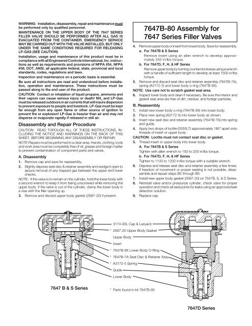
3174-93L Cap & Lanyard<br />
* 2697-20 Upper Body Gasket<br />
Upper Body<br />
Insert<br />
* 7647B-9X Lower Body O-Ring<br />
* 7647B-7A Seat Disc & Retainer Assy.<br />
* A3172-5 Spring<br />
Guide<br />
Lower Body<br />
7647 B & S Series<br />
* <strong>Part</strong>s found in kit 7647B-80<br />
7647D Series


