

Repair Kits Available By Part Number Section 2 Page - GAMECO
Repair Kits Available By Part Number Section 2 Page - GAMECO
Repair Kits Available By Part Number Section 2 Page - GAMECO

You also want an ePaper? Increase the reach of your titles
YUMPU automatically turns print PDFs into web optimized ePapers that Google loves.
WARNING: Installation, disassembly, repair and maintenance must<br />
be performed only by qualified personnel.<br />
All gas MUST be evacuated from the system before starting<br />
repairs.<br />
Installation, usage and maintenance of this product must be in<br />
compliance with all Engineered Controls International, Inc. instructions<br />
as well as requirements and provisions of NFPA #54, NFPA<br />
#58, DOT, ANSI, all applicable federal, state, provincial and local<br />
standards, codes, regulations and laws.<br />
Inspection and maintenance on a periodic basis is essential.<br />
Be sure all instructions are read and understood before installation,<br />
operation and maintenance. These instructions must be<br />
passed along to the end user of the product.<br />
CAUTION: Contact or inhalation of liquid propane, ammonia and<br />
their vapors can cause serious injury or death! NH3 and LP-Gas<br />
must be released outdoors in air currents that will insure dispersion<br />
to prevent exposure to people and livestock. LP-Gas must be kept<br />
far enough from any open flame or other source of ignition to<br />
prevent fire or explosion! LP-Gas is heavier than air and may not<br />
disperse or evaporate rapidly if released in still air.<br />
Disassembly and <strong>Repair</strong> Procedure<br />
CAUTION: READ THROUGH ALL OF THESE INSTRUCTIONS, IN-<br />
CLUDING THE NOTICE AND WARNINGS ON THE BACK OF THIS<br />
SHEET, BEFORE BEGINNING ANY DISASSEMBLY OR REPAIR.<br />
NOTE: <strong>Repair</strong>s must be performed in a clean area. Hands, clothing,<br />
tools and work area must be completely free of oil, grease and foreign<br />
matter to prevent contamination of component parts and valves.<br />
A. Disassembly<br />
1. Completely shut-off gas supply to the coupling, both upstream and<br />
downstream.<br />
2. Safely disconnect the male half from the female half of the coupling.<br />
CAUTION: Protective eyewear and gloves must be worn when<br />
disconnecting the coupling.<br />
3. Safely remove internal pressure from lines both upstream and<br />
downstream of the coupling.<br />
4. Remove the white teflon washer and o-ring from the groove inside<br />
the female coupling half. Use a plastic or wood tool so as not to<br />
scratch or nick the surface of the groove. Retain the white teflon<br />
washer and discard the o-ring.<br />
5. Clean both coupling halves.<br />
6. Inspect the male coupling half for damage. If there is damage to the<br />
sealing area of poppet, remove and discard the male half and<br />
replace with a new male coupling — #A2141A6M for the 3 /4" and<br />
#A2141A8M for the 1".<br />
A2141A6-50, A2141A8-50<br />
A2141A6M and A2141A8M<br />
<strong>Repair</strong> <strong>Kits</strong> for A2141A6 and<br />
A2141A8 Pull-Away Couplings<br />
Kit<br />
For<br />
<strong>Number</strong> <strong>Repair</strong> Of Contents<br />
A2141A6-50 A2141A6 (1) O-Ring<br />
A2141A8-50 A2141A8 (1) O-Ring<br />
A2141A6M A2141A6 (1) 3<br />
/4" Male Coupling<br />
A2141A8M A2141A8 (1) 1" Male Coupling<br />
B. Reassembly<br />
1. Be sure the seal groove is clean in the female coupling. Lightly<br />
lubricate the groove with hydraulic oil or petroleum grease.<br />
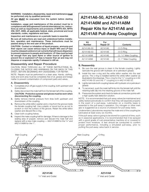
2. Install the new o-ring and the white teflon washer into the seal<br />
groove. The o-ring is installed behind the white teflon washer as<br />
illustrated in the drawings. The o-ring for the 3 /4" coupling is in Kit<br />
#A2141A6-50 and the 1" coupling is in #A2141A8-50.<br />
3. Lightly lubricate both coupling halves with hydraulic oil or petroleum<br />
grease.<br />
4. To reconnect, push the male half firmly into the female half until the<br />
retaining balls slip into the retaining groove of the male half.<br />
5. Pressurize the system and check for leaks at connection points with<br />
a high quality leak detection solution.<br />
NOTE: It is recommended that pull-away valves be maintained and<br />
safely tested periodically to confirm that they will separate properly<br />
in the event of a pull-away. Lubrication on a monthly basis is<br />
essential to the pull-away’s operation. Dry nitrogen or other inert<br />
gas is suggested as a source of pressure for pull-away tests.<br />
Underwriters Laboratories requires the male end of the coupling be<br />
lubricated at least every six months.<br />
If the pull-away valve is going to be stored for a period of time, such<br />
as in seasonal applications, it is recommended that it be sprayed<br />
with a good grade of rust-preventative machine oil or covered to<br />
protect from moisture. A test should be conducted to confirm<br />
proper performance, including a simulated pull-away, prior to<br />
putting the pull-away valve back in service.<br />
Male Coupling<br />
O-Ring<br />
Male Coupling<br />
O-Ring<br />
A2141A6<br />
3<br />
/4" Inlet and Outlet<br />
A2141A8<br />
1" Inlet and Outlet


