

Repair Kits Available By Part Number Section 2 Page - GAMECO
Repair Kits Available By Part Number Section 2 Page - GAMECO
Repair Kits Available By Part Number Section 2 Page - GAMECO

You also want an ePaper? Increase the reach of your titles
YUMPU automatically turns print PDFs into web optimized ePapers that Google loves.
WARNING: Installation, disassembly, repair and maintenance<br />
must be performed only by qualified personnel.<br />
All gas MUST be evacuated from the system before starting<br />
repairs.<br />
Installation, usage and maintenance of this product must be in<br />
compliance with all Engineered Controls International, Inc. instructions<br />
as well as requirements and provisions of NFPA #54, NFPA<br />
#58, DOT, ANSI, all applicable federal, state, provincial and local<br />
standards, codes, regulations and laws.<br />
Inspection and maintenance on a periodic basis is essential.<br />
Be sure all instructions are read and understood before installation,<br />
operation and maintenance. These instructions must be<br />
passed along to the end user of the product.<br />
CAUTION: Contact or inhalation of liquid propane, ammonia and<br />
their vapors can cause serious injury or death! NH 3<br />
and LP-Gas<br />
must be released outdoors in air currents that will insure dispersion<br />
to prevent exposure to people and livestock. LP-Gas must be kept<br />
far enough from any open flame or other source of ignition to<br />
prevent fire or explosion! LP-Gas is heavier than air and may not<br />
disperse or evaporate rapidly if released in still air.<br />
Disassembly and <strong>Repair</strong> Procedure<br />
CAUTION: READ THROUGH ALL OF THESE INSTRUCTIONS IN-<br />
CLUDING THE NOTICE AND WARNINGS ON THE BACK OF THIS<br />
SHEET BEFORE BEGINNING ANY DISASSEMBLY OR REPAIR.<br />
NOTE: <strong>Repair</strong>s must be performed in a clean area. Hands, clothing,<br />
tools and work area must be completely free of oil, grease and foreign<br />
matter to prevent contamination of component parts and valves.<br />
A. Disassembly<br />
1. EVACUATE ALL GAS FROM THE SYSTEM BEFORE ANY DISAS-<br />
SEMBLY OR REPAIR. Turn adjusting screw clockwise as far as it<br />
will go and wait until there is no pressure in the regulator body. Then<br />
remove regulator from system completely before performing disassembly<br />
or repairs.<br />
2. Loosen locknut and turn adjusting screw counterclockwise until<br />
spring tension is released.<br />
REGULATOR REPAIR KITS<br />
AA1582E-50 FOR AA1582E SERIES<br />
AA1584E-50 FOR AA1584E SERIES<br />
AA1586E-50 FOR AA1586E SERIES<br />
3. Use a wrench to turn backcap counterclockwise. Remove backcap<br />
and save for reassembly. Remove and discard small spring.<br />
4. Unthread stem & seat disc retainer assembly from yoke by turning<br />
counterclockwise with a wrench. Remove and discard.<br />
5. Remove the six bonnet screws and save for reassembly.<br />
6. Separate the bonnet from the regulator body. Remove spring<br />
button, large spring, and the diaphragm & yoke assembly. Save the<br />
spring button and large spring for reassembly. Discard diaphragm<br />
& yoke assembly.<br />
NOTE: If either of the two diaphragms stick to the body, they must<br />
be pulled free with care to allow removal of the assembly.<br />
7. Inspect inside of body and clean if necessary. Body must be free of<br />
dirt, residue and foreign particles.<br />
B. Reassembly<br />
NOTE: Do not install the new diaphragm & yoke assembly unless the<br />
holes in the upper and lower diaphragms are aligned.<br />
1. Install the new diaphragm & yoke assembly in the body with the<br />
white teflon diaphragm facing body assembly.<br />
2. Inspect the seat of new stem & seat disc assembly. It must be free<br />
of foreign material. Install new stem & seat disc retainer assembly by<br />
threading clockwise into the yoke and tightening with a wrench.<br />
3. Position the spring button on the large spring and place them<br />
together on the diaphragm plate.<br />
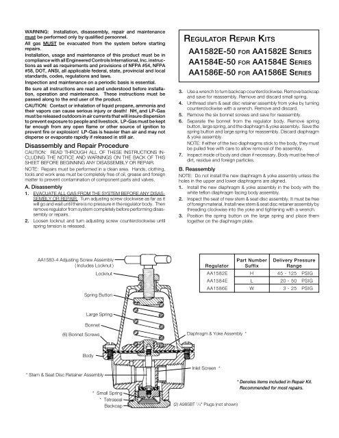
AA1583-4 Adjusting Screw Assembly<br />
( Includes Locknut )<br />
Locknut<br />
Spring Button<br />
<strong>Part</strong> <strong>Number</strong> Delivery Pressure<br />
Regulator Suffix Range<br />
AA1582E H 45 - 125 PSIG<br />
AA1584E L 20 - 50 PSIG<br />
AA1586E W 3 - 25 PSIG<br />
Large Spring<br />
Bonnet<br />
(6) Bonnet Screws<br />
Diaphragm & Yoke Assembly *<br />
Body<br />
* Stem & Seat Disc Retainer Assembly<br />
* Small Spring<br />
* Tetraseal<br />
Backcap<br />
Inlet Screen *<br />
(2) A985BT 1 /4" Plugs (not shown)<br />
* Denotes items included in <strong>Repair</strong> Kit.<br />
Recommended for most repairs.


