

Repair Kits Available By Part Number Section 2 Page - GAMECO
Repair Kits Available By Part Number Section 2 Page - GAMECO
Repair Kits Available By Part Number Section 2 Page - GAMECO

You also want an ePaper? Increase the reach of your titles
YUMPU automatically turns print PDFs into web optimized ePapers that Google loves.
WARNING: Installation, disassembly, repair and maintenance must<br />
be performed only by qualified personnel.<br />
Complete maintenance should be performed only after all gas has<br />
been evacuated from the system and container. Remove the entire<br />
valve before performing repairs, except as noted below.<br />
Emergency service, on the actuator and lower stem assembly<br />
portion of the valve only, may be carried out with the valve installed,<br />
provided downstream pressure is relieved under the same conditions<br />
required for releasing LP-Gas, as in the caution below, and<br />
that there is positive assurance that the valve is closed tight with<br />
no leakage past the seats.<br />
Installation, usage and maintenance of this product must be in<br />
compliance with all Engineered Controls International, Inc. instructions<br />
as well as requirements and provisions of NFPA #54, NFPA<br />
#58, DOT, ANSI, all applicable federal, state, provincial and local<br />
standards, codes, regulations and laws.<br />
Inspection and maintenance on a periodic basis is essential.<br />
Be sure all instructions are read and understood before installation,<br />
operation and maintenance. These instructions must be<br />
passed along to the end user of the product.<br />
CAUTION: Contact or inhalation of liquid propane, ammonia and<br />
their vapors can cause serious injury or death! NH3 and LP-Gas<br />
must be released outdoors in air currents that will insure dispersion<br />
to prevent exposure to people and livestock. LP-Gas must be kept<br />
far enough from any open flame or other source of ignition to<br />
prevent fire or explosion! LP-Gas is heavier than air and may not<br />
disperse or evaporate rapidly if released in still air.<br />
Disassembly and <strong>Repair</strong> Procedure<br />
CAUTION: READ THROUGH ALL OF THESE INSTRUCTIONS, IN-<br />
CLUDING THE NOTICE AND WARNINGS ON THE BACK OF THIS<br />
SHEET, BEFORE BEGINNING ANY DISASSEMBLY OR REPAIR.<br />
NOTE: Before repairing valve, thoroughly examine valve lever and all<br />
associated parts for excessive wear. Check lever for proper function and<br />
threads for excessive wear and damage. Any components that are not in<br />
good condition and fully operational should be replaced during repairs.<br />
<strong>Repair</strong>s must be performed in a clean area. Hands, clothing, tools and<br />
work area must be completely free of oil, grease and foreign matter to<br />
prevent contamination of component parts and valves. Clean the valve<br />
body and all parts before assembly.<br />
Disassembly<br />
Actuator / Lower Stem Assembly—<br />
1. Clamp the valve body horizontally in a vise with the actuator portion<br />
overhanging the end of the vise and the outlet facing upwards. Be<br />
careful not to clamp by the threads.<br />
2. Loosen the three (3) hex screws and remove the entire lever housing<br />
assembly. Set aside for reassembly.<br />
3. Remove the lower retaining ring, cup washer and external return<br />
spring from the lower stem by first pushing down on the cup washer<br />
and/or spring to expose the ring and then disengage the ring.<br />
Discard the retaining ring and save the spring and cup washer for<br />
reassembly.<br />
4. Using a 13 /16" wrench, completely loosen and remove the seal<br />
housing. The entire stem assembly may come out at this time. If not,<br />
work through the outlet opening of the body while pulling on the<br />
lower stem to remove it and the bushing.<br />
5. Remove the two (2) seal rings, the jam ring and o-ring from the seal<br />
housing and discard. Save the washer for reassembly.<br />
6. Remove the bushing and upper retaining ring from the lower stem<br />
and discard.<br />
7. Remove the gasket from the body and discard.<br />
8. Retain the washer and packing spring for reassembly.<br />
9. Check the lower stem [A3210-2] for excessive wear and/or damage,<br />
especially in the seal ring area. Replace if necessary.<br />
Seat Disc/Body Assembly—<br />
1. Hold the hex of the upper stem with a 3 /8" socket working from the<br />
lower stem opening of the valve body. Remove the disc retaining<br />
screw, being careful to hold down the main seat disc assembly as<br />
it is spring loaded and will pop off suddenly. Retain the disc retaining<br />
screw for reassembly.<br />
A3210A-50 <strong>Repair</strong> Kit<br />
for A3210A Series<br />
1 1 /4" Angle Internal Valves<br />
2. Remove and discard the main seat disc assembly. Remove and<br />
retain the excess flow spring.<br />
3. Remove and retain the upper stem and internal return spring.<br />
4. Remove the seat disc from the disc retaining screw. Discard the<br />
seat disc.<br />
5. Check the upper stem [A3210-10] for excessive wear. Replace if<br />
necessary.<br />
Reassembly<br />
Seat Disc/Body Assembly—<br />
1. Assemble the new seat disc onto the disc retaining screw.<br />
2. Apply a thin coat of #11550-215 compound to the upper stem.<br />
3. Place the internal return spring over the upper stem. Holding the<br />
upper stem with a 3 /8" socket, guide it into the valve body through<br />
the lower stem opening of the valve body.<br />
4. While a third hand pushes the upper stem forward through the valve<br />
guide at the inlet, reassemble the excess flow spring and new main<br />
seat disc assembly onto the protruding end of the upper stem and<br />
hold in place for step five.<br />
5. Apply #11550-571 compound to the threads of the disc retaining<br />
screw and screw it into the end of the upper stem. Torque down to<br />
40-45 in/lbs.<br />
CAUTION: Do not allow #11550-571 compound to contact seat<br />
disc. Use sparingly.<br />
6. Check for smooth operation of the upper stem and proper seating<br />
of the springs by pushing on the lower stem to open and close the<br />
seats.<br />
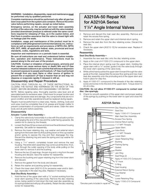
A3210A Series<br />
Hex<br />
Screw<br />
*Denotes parts included in repair kit.<br />
Disc Retaining Screw<br />
* Seat Disc<br />
* Apply 11550-571 Compound<br />
* Main Seat Disc Assembly<br />
Excess Flow Spring<br />
Internal Return spring<br />
1 1 /4" NPT Threads<br />
Upper Stem<br />
Valve Body<br />
1 1 /4" NPT Threads<br />
Lower Stem<br />
* Upper Retaining Ring<br />
* Bushing<br />
Packing Spring<br />
* Gasket<br />
Washer<br />
* Jam Ring<br />
* Seal Rings (2)<br />
* Apply #11550-215 Compound<br />
“S” Hook<br />
* O-Ring<br />
Seal Housing<br />
External Return Spring<br />
Cup Washer<br />
Lever<br />
* Lower Retaining Ring<br />
* Apply 11550-215 Compound<br />
Cap


