

Repair Kits Available By Part Number Section 2 Page - GAMECO
Repair Kits Available By Part Number Section 2 Page - GAMECO
Repair Kits Available By Part Number Section 2 Page - GAMECO

Create successful ePaper yourself
Turn your PDF publications into a flip-book with our unique Google optimized e-Paper software.
WARNING: Installation, usage and maintenance of this product<br />
must be in compliance with all Engineered Controls International,<br />
Inc. instructions as well as requirements and provisions of NFPA<br />
#54, NFPA #58, DOT and all applicable federal, state, provincial<br />
and local standards, codes, rules, regulations and laws.<br />
Inspection and maintenance on a periodic basis is essential.<br />
Installation and maintenance should be performed only by qualified<br />
personnel.<br />
Be sure all instructions are read and understood before installation<br />
and operation.<br />
CAUTION: Contact or inhalation of liquid propane, ammonia and<br />
their vapors can cause serious injury or death! NH3 and LP-Gas<br />
must be released outdoors in air currents that will insure dispersion<br />
to prevent exposure to people and livestock. LP-Gas must be kept<br />
far enough from any open flame or other source of ignition to<br />
prevent fire or explosion! LP-Gas is heavier than air and will not<br />
disperse or evaporate rapidly if released in still air.<br />
Foreword<br />
The A3209PA Pneumatic Actuator is designed especially for use with<br />
the A3209A Series Internal Valves. It is designed to provide a convenient<br />
means for opening and closing the valve from a remote location.<br />
Responsibility for proper installation must be met by the installer.<br />
How the Pneumatic Actuator Works<br />
The pneumatic actuator can be pressurized with either air or nitrogen.<br />
The actuator’s diaphragm rod moves the valve’s operating lever to the<br />
open position when pressure is applied. Upon loss of pressure, the<br />
valve’s operation lever returns to the closed position. The A3209PA<br />
operates with a minimum pressure of 50 psig and a maximum operation<br />
pressure of 250 psig.<br />
The A3209PA pneumatic actuator is compatible with existing air interlock<br />
systems. It also provides a convenient means of operating a<br />
number of internal valves on stationary storage tanks at bulk plants from<br />
remote locations.<br />
Pneumatic Actuator Installation<br />
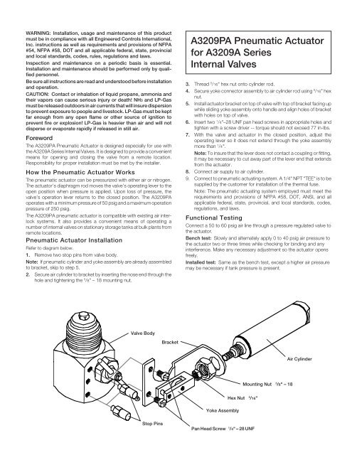
Refer to diagram below.<br />
1. Remove two stop pins from valve body.<br />
Note: If pneumatic cylinder and yoke assembly are already assembled<br />
to bracket, skip to step 5.<br />
2. Secure air cylinder to bracket by inserting the nose end through the<br />
hole and tightening the 5 /8" – 18 mounting nut.<br />
A3209PA Pneumatic Actuator<br />
for A3209A Series<br />
Internal Valves<br />
3. Thread 5 /16" hex nut onto cylinder rod.<br />
4. Secure yoke connector assembly to air cylinder rod using 5 /16" hex<br />
nut.<br />
5. Install actuator bracket on top of valve with top of bracket facing up<br />
while sliding yoke assembly onto handle and align holes of bracket<br />
with holes on top of valve.<br />
6. Insert two 1 /4"–28 UNF pan head screws in appropriate holes and<br />
tighten with a screw driver -- torque should not exceed 77 in-lbs.<br />
7. With the valve and actuator in the closed position, adjust the<br />
operating lever so it does not extend through the yoke assembly<br />
more than 1 /4".<br />
Note: To insure that the lever does not contact a coupling or fitting,<br />
it may be necessary to cut away part of the lever end that extends<br />
from the actuator.<br />
8. Connect air supply to air cylinder.<br />
9. Connect to pneumatic actuating system. A 1/4" NPT "TEE" is to be<br />
supplied by the customer for installation of the thermal fuse.<br />
Note: The pneumatic actuating system employed must meet the<br />
requirements and provisions of NFPA #58, DOT, ANSI, and all<br />
applicable federal, state, provincial, and local standards, codes,<br />
regulations, and laws.<br />
Functional Testing<br />
Connect a 50 to 60 psig air line through a pressure regulated valve to<br />
the actuator.<br />
Bench test: Slowly and alternately apply 0 to 40 psig air pressure to<br />
the actuator two or three times while checking for binding and any<br />
interference. Make any necessary adjustment so the actuator opens<br />
freely.<br />
Installed test: Same as the bench test, except a higher air pressure<br />
may be necessary if tank pressure is present.<br />
Valve Body<br />
Bracket<br />
Air Cylinder<br />
Mounting Nut 5<br />
/8" – 18<br />
Hex Nut 5<br />
/16"<br />
Yoke Assembly<br />
Stop Pins<br />
Pan Head Screw 1<br />
/4" – 28 UNF


