

Repair Kits Available By Part Number Section 2 Page - GAMECO
Repair Kits Available By Part Number Section 2 Page - GAMECO
Repair Kits Available By Part Number Section 2 Page - GAMECO

Create successful ePaper yourself
Turn your PDF publications into a flip-book with our unique Google optimized e-Paper software.
WARNING: Installation, disassembly, repair and maintenance<br />
must be performed only by qualified personnel.<br />
All gas MUST be evacuated from the system before starting<br />
repairs.<br />
Installation, usage and maintenance of this product must be in<br />
compliance with all Engineered Controls International, Inc. instructions<br />
as well as requirements and provisions of NFPA #54, NFPA<br />
#58, DOT, ANSI, all applicable federal, state, provincial and local<br />
standards, codes, regulations and laws.<br />
Inspection and maintenance on a periodic basis is essential.<br />
Be sure all instructions are read and understood before installation,<br />
operation and maintenance. These instructions must be<br />
passed along to the end user of the product.<br />
CAUTION: Contact or inhalation of liquid propane, ammonia and<br />
their vapors can cause serious injury or death! NH3 and LP-Gas<br />
must be released outdoors in air currents that will insure dispersion<br />
to prevent exposure to people and livestock. LP-Gas must be kept<br />
far enough from any open flame or other source of ignition to<br />
prevent fire or explosion! LP -Gas is heavier than air and may not<br />
disperse or evaporate rapidly if released in still air.<br />
NOTE: When servicing obsolete 3100 and 7100 Series cylinder<br />
valves, a conversion to the o-ring style trim is preferred to straight<br />
repair. The o-ring style assembly provides construction that is<br />
more resistant to over-torquing on closure or opening to the backseated<br />
position. Installation in the field is easier, due to metal-tometal<br />
makeup between the body and bonnet and the elimination of<br />
retaining compound as a thread sealant. Order Engineered Controls<br />
International, Inc. repair kit 3100-81K for conversion to the o-<br />
ring style.<br />
Disassembly and <strong>Repair</strong> Procedure<br />
CAUTION: READ THROUGH ALL OF THESE INSTRUCTIONS,<br />
INCLUDING THE NOTICE AND WARNINGS ON THE BACK OF<br />
THIS SHEET, BEFORE BEGINNING ANY DISASSEMBLY OR RE-<br />
PAIR.<br />
NOTE: <strong>Repair</strong>s must be performed in a clean area. Hands, clothing,<br />
tools and work area must be completely free of oil, grease and foreign<br />
matter to prevent contamination of component parts and valves.<br />
A. Disassembly<br />
1. EVACUATE ALL GAS FROM THE SYSTEM BEFORE ANY<br />
DISASSEMBLY OR REPAIR. Turn handwheel counter clockwise<br />
as far as it will go to release any gas remaining in the container.<br />
CAUTION: Do not apply force after valve is fully open and backseated.<br />
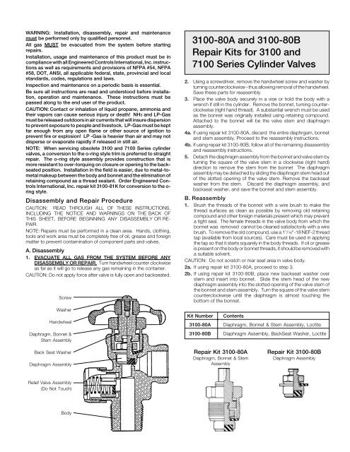
Screw<br />
Washer<br />
Handwheel<br />
Diaphragm, Bonnet &<br />
Stem Assembly<br />
3100-80A and 3100-80B<br />
<strong>Repair</strong> <strong>Kits</strong> for 3100 and<br />
7100 Series Cylinder Valves<br />
2. Using a screwdriver, remove the handwheel screw and washer by<br />
turning counterclockwise--thus allowing removal of the handwheel.<br />
Save these parts for reassembly.<br />
3. Place the valve body securely in a vise or hold the body with a<br />
wrench if still in the cylinder. Remove the bonnet, turning counterclockwise<br />
(right hand thread). A substantial wrench must be used<br />
as the bonnet was originally installed using retaining compound.<br />
Attached to the bonnet will be the valve stem and diaphragm<br />
assembly.<br />
4a. If using repair kit 3100-80A, discard the entire diaphrgam, bonnet<br />
and stem assembly. Proceed to the reassembly instructions.<br />
4b. If using repair kit 3100-80B, follow all of the remaining disassembly<br />
and reassembly instructions.<br />
5. Detach the diaphragm assembly from the bonnet and valve stem by<br />
turning the square of the valve stem in a clockwise (right hand)<br />
direction to remove the stem from the bonnet The diaphragm<br />
assembly may be detached by sliding the diaphragm stem head out<br />
of the slotted opening of the valve stem. Remove the backseat<br />
washer from the stem. Discard the diaphragm assembly, and<br />
backseat washer, and save the bonnet and stem assembly.<br />
B. Reassembly<br />
1. Brush the threads of the bonnet with a wire brush to make the<br />
thread surfaces as clean as possible by removing old retaining<br />
compound and other foreign materials present which may prevent<br />
a tight seal. The female threads in the valve body from which the<br />
bonnet was removed cannot be cleaned satisfactorily with a wire<br />
brush. To remove the old compound, use a 1 1 /16"-18 NEF-2 thread<br />
tap (available from local sources). Care must be used in applying<br />
the tap so that it starts squarely in the body threads. If oil or grease<br />
is present on the body or bonnet threads, it should be removed with<br />
a suitable solvent.<br />
CAUTION: Do not scratch or mar seat area in valve body.<br />
2a. If using repair kit 3100-80A, proceed to step 3.<br />
2b. If using repair kit 3100-80B, place new backseat washer over<br />
stem and insert into bonnet. Slide the stem head of the new<br />
diaphragm assembly into the slotted opening of the valve stem of<br />
the bonnet and stem assembly. Turn the square of the valve stem<br />
counterclockwise until the diaphragm is almost touching the<br />
bottom of the bonnet.<br />
Kit <strong>Number</strong><br />
Contents<br />
3100-80A Diaphragm, Bonnet & Stem Assembly, Loctite<br />
3100-80B Diaphragm Assembly, BackSeat Washer, Loctite<br />
Back Seat Washer<br />
Diaphragm Assembly<br />
<strong>Repair</strong> Kit 3100-80A<br />
Diaphragm, Bonnet & Stem<br />
Assembly<br />
<strong>Repair</strong> Kit 3100-80B<br />
Diaphragm Assembly<br />
Relief Valve Assembly<br />
(Do Not Touch)<br />
Body


