1 Turn off the power of the printer. - Van Mechelen
1 Turn off the power of the printer. - Van Mechelen
1 Turn off the power of the printer. - Van Mechelen
- No tags were found...

Create successful ePaper yourself
Turn your PDF publications into a flip-book with our unique Google optimized e-Paper software.
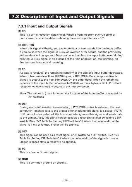
7.3 Description <strong>of</strong> Input and Output Signals<br />
7.3.1 Input and Output Signals<br />
(1) RD<br />
This is a serial reception data signal. When a framing error, overrun error or<br />
parity error occurs, <strong>the</strong> data containing <strong>the</strong> error is printed as a “”.<br />
(2) DTR, RTS<br />
When this signal is Ready, you can write data or commands into <strong>the</strong> input buffer.<br />
If you do so while <strong>the</strong> signal is Busy, an overrun error occurs, and <strong>the</strong> previously<br />
written data will be ignored. Data can be written into <strong>the</strong> input buffer even during<br />
printing. A Busy signal is also issued at <strong>the</strong> time <strong>of</strong> <strong>power</strong>-on, test printing, online<br />
communication, and resetting.<br />
(3) TD<br />
As data is received, <strong>the</strong> remaining capacity <strong>of</strong> <strong>the</strong> <strong>printer</strong>’s input buffer decreases.<br />
When it becomes less than 128(10) bytes, a DC3 (13H) (Data reception disable<br />
signal) is output to <strong>the</strong> host computer. On <strong>the</strong> o<strong>the</strong>r hand, when <strong>the</strong> remaining<br />
capacity <strong>of</strong> <strong>the</strong> input buffer increases to 256(20) or more bytes, a DC1 (11H)(Data<br />
reception enable signal) is output to <strong>the</strong> host computer.<br />
Note: The values in ( ) are for when <strong>the</strong> 72 bytes <strong>of</strong> <strong>the</strong> input buffer is selected by<br />
DIP switches.<br />
(4) DSR<br />
During status information transmission, if DTR/DSR control is selected, <strong>the</strong> host<br />
computer transfers data to <strong>the</strong> <strong>printer</strong> after checking this signal is a space. If DTR/<br />
DSR control is not selected, <strong>the</strong> host computer ignores this signal and sends data<br />
to <strong>the</strong> <strong>printer</strong>. Also, this signal can be used as a reset signal after switching a DIP<br />
switch. (See “5.2 Table for Setting DIP Switches”.) When <strong>the</strong> pulse width <strong>of</strong> <strong>the</strong><br />
signal is 1 ms or longer, a reset will be applied.<br />
(5) INIT<br />
This signal can be used as a reset signal after switching a DIP switch. (See “5.2<br />
Table for Setting DIP Switches”.) When <strong>the</strong> pulse width <strong>of</strong> <strong>the</strong> signal is 1 ms or<br />
longer in space state, a reset will be applied.<br />
(6) FG<br />
This is a Frame Ground signal.<br />
(7) GND<br />
This is a common ground on circuits.<br />
— 34 —