Create successful ePaper yourself
Turn your PDF publications into a flip-book with our unique Google optimized e-Paper software.
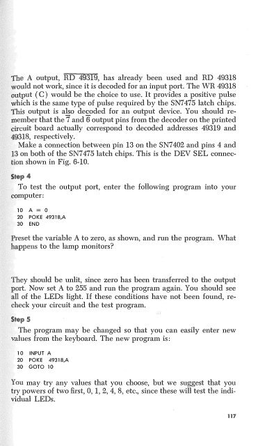
The A output, RD 49319, has already been used and RD 49318<br />
not work, since it is decoded for an input port. The WR 49318<br />
output ( C ) would be the choice to use. It provides a positive pulse<br />
which. is the same type of pulse required by the SN7475 latch chips.<br />
This output is ao de£.oded for an output device. You should remember<br />
that the 7 and 6 output pins from the decoder on the printed<br />
circuit board actually correspond to decoded addresses 49319 and<br />
49318, respectively.<br />
Make a connection between pin 13 on the SN7402 and pins 4 and<br />
13 on both of the SN7475 latch chips. This is the DEV SEL connection<br />
shown in Fig. 6-10.<br />
To test the output port, enter the following program into your<br />
computer:<br />
10 A= 0<br />
20 POKE 49318,A<br />
30 END<br />
Preset the variable A to zero, as shown, and run the program. What<br />
happens to the lamp monitors<br />
They should be unlit, since zero has been transferred to the output<br />
pmt Now set A to 255 and nm the program again. You should see<br />
all of the LEDs light. If these conditions have not been found, recheck<br />
your circuit and the test program.<br />
The program may be changed so that you can easily enter new<br />
values from the keyboard. The new program is:<br />
10 INPUT A<br />
20 POKE 49318,A<br />
30 GOTO 10<br />
You may try any values that you choose, but we suggest that you<br />
try powers of two first, 0, 1, 2, 4, 8, etc., since these will test the individual<br />
LEDs.<br />
117


