


Create successful ePaper yourself
Turn your PDF publications into a flip-book with our unique Google optimized e-Paper software.
The actual ORing of these control signals is performed by the<br />
SN74LS20 gate, IC-8. The INPUT REQUEST signal that is output<br />
y this 4-input NAND gate is further gated with OUT and WR. This<br />
ting provides a safety interlock, so that if your breadboard circuits<br />
ave been improperly wired, the bus drivers cannot be placed in the<br />
put mode when an output-type operation is taking place. The reltant<br />
"INPUT REQUEST, BUT NOT OUT OR WR" signal conols<br />
the input/ output mode of the 8216 bus buffers.<br />
Since the Apple generates only the memory write signal, WR, this<br />
imply means that your interface will not be able to tum the bus<br />
.itround for an input operation, when the computer is performing a<br />
rite operation. The OUT signal is used for <strong>interfacing</strong> with 8080,<br />
85, or Z-80 computers.<br />
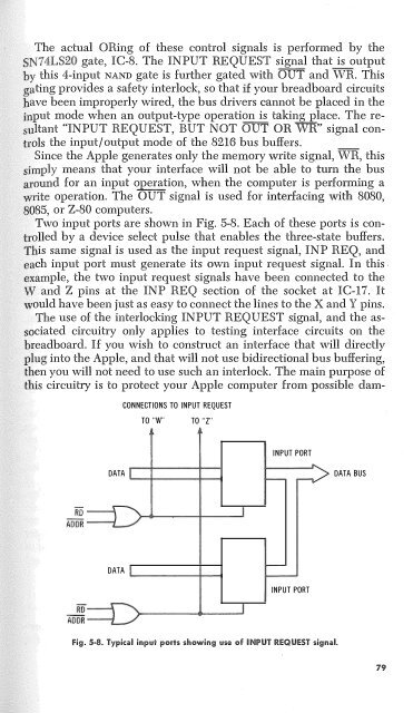
Two input ports are shown in Fig. 5-8. Each of these ports is conolled<br />
by a device select pulse that enables the three-state buffers.<br />
is same signal is used as the input request signal, INP REQ, and<br />
ch input port must generate its own input request signal. In this .<br />
ample, the two input request signals have been connected to the<br />
and Z pins at the INP REQ section of the socket at IC-17. It<br />
ould have been just as easy to connect the lines to the X and Y pins.<br />
The use of the interlocking INPUT REQUEST signal, and the asciated<br />
·circuitry only applies to testing interface circuits on the<br />
readboard. If you wish to construct an interface that will directly<br />
lug into the Apple, and that will not use bidirectional bus buffering,<br />
en you will not need to use such an interlock. The main purpose of<br />
is circuitry is to protect your Apple computer from possible dam-<br />
CONNECTIONS TO INPUT REQUEST<br />
TO "W"<br />
TO "Z"<br />
INPUT PORT<br />
DATA<br />
'---+----1----i<br />
DATA BUS<br />
DATA<br />
..._ ____ ,____,<br />
INPUT PORT<br />
Fig. 5·8. Typical input ports showing use of INPUT REQUEST signal.<br />
79


