- Page 1 and 2:
lJ. 21862 APPLE® INTERFACING JONAT
- Page 3 and 4:
APPLE® INTERFACING by Jonathan A.
- Page 5 and 6:
Preface The purpose in writing this
- Page 7 and 8:
make no attempt to provide much det
- Page 9 and 10:
Contents CHAPTER 1 6502 PROCESSOR 9
- Page 11 and 12:
CHAPTER 1 6502 Processor The Apple
- Page 13 and 14:
Fig. 1- 1. 6502 Microprocessor chip
- Page 15 and 16: locate the memory "cell" that is to
- Page 17 and 18: IR.,view At this point, you should
- Page 19 and 20: Gei'!eral-fi!Jrp@S('; I/ 0 Commaru:
- Page 21 and 22: of an examined memory location. Fro
- Page 23 and 24: will now explore the actions that e
- Page 25 and 26: transfers will require more than ei
- Page 27 and 28: grams are probably easier to write
- Page 29 and 30: ·when the Apple computer is progrn
- Page 31 and 32: Y@bie ::!1. VNth i
- Page 33 and 34: DECODED OUTPUT puter systems, the R
- Page 35 and 36: 1 1 1 Using Decoders In many cases,
- Page 37 and 38: used in PEEK commands, for example
- Page 39 and 40: An alternate approach is to use bot
- Page 41 and 42: sections, but the address inputs, A
- Page 43 and 44: fUNCTlON TABLES COMPARING CASCADING
- Page 45 and 46: flexible decoding scheme, as shown
- Page 47 and 48: until the power is turned off. Ther
- Page 49 and 50: the logic zero state. In most cases
- Page 51 and 52: ue in sequence (in binary), 255, 25
- Page 53 and 54: DATA BUS DATA A SN74125 DATA B DATA
- Page 55 and 56: R gates that control the enabling o
- Page 57 and 58: state of the unused bits cannot be
- Page 59 and 60: CHAPTER 4 Flags and Decisions n alm
- Page 61 and 62: VALUE 00111010 00011010 11110000 00
- Page 63 and 64: •• Addrss Byte Da;a Syie Mexacl
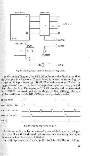
- Page 65: INPUT DEVICE RD 49321 - READY/BUSY
- Page 69 and 70: y-language programming will also be
- Page 71 and 72: CHAPTER 5 Breadboarding 01 With the
- Page 73 and 74: 5 IN4001 (4) 6 ,.___'-'' N:...J LM3
- Page 75 and 76: A15 AIO A13 Al2 Al4 All A9 AfJ D .L
- Page 77 and 78: In the memory address mode, must pl
- Page 79 and 80: PIN CONFIGURATION DJ, LOGIC DIAGRAM
- Page 81 and 82: The actual ORing of these control s
- Page 83 and 84: Fig. 5·10. Packaged version of the
- Page 85 and 86: SIGNAL APPLE PfN INTERFACE PIN +12V
- Page 87 and 88: ·.chips have rather slow access ti
- Page 89 and 90: are possible, we think that one exp
- Page 91 and 92: in most of the experiments unless o
- Page 93 and 94: tep 3 You may wish to test other po
- Page 95 and 96: ,..,,.,....,"'"' in the block from
- Page 97 and 98: None of the outputs should be activ
- Page 99 and 100: ---" 2 CLR 20 2 CK Si\17474 The dev
- Page 101 and 102: entered and run, It first asks you
- Page 103 and 104: +5 Gl\ID LOGIC SWITCHES A B c D 16
- Page 105 and 106: PR INT "O"; GOTO 65 If you wish to
- Page 107 and 108: am, and the two-byte decimal calcul
- Page 109 and 110: for each value that is input to the
- Page 111 and 112: of the monitor screen each time the
- Page 113 and 114: A = 128 420 B = PEEK(493 l 9) 430 F
- Page 115 and 116: il!!lie -2. 0 THEN . . .
- Page 117 and 118:
program. You may forgotten steps to
- Page 119 and 120:
The A output, RD 49319, has already
- Page 121 and 122:
used the following program: FOR A =
- Page 123 and 124:
· numbers would have to be "split"
- Page 125 and 126:
tep 1 The input port and output por
- Page 127 and 128:
0'"""c"y'·i- the relative values t
- Page 129 and 130:
and output ports are simply additio
- Page 131 and 132:
e has been divided into 256 values,
- Page 133 and 134:
e converter will not burn out, sinc
- Page 135 and 136:
07 DATA BUS DO 3 4 7 a 13 14 17 18
- Page 137 and 138:
each decade. The bed code is used i
- Page 139 and 140:
LED BIT RED } D3 YELLOW EL M D4 GRE
- Page 141 and 142:
: : FOR T = 0 TO 770 NEX T T NEX T
- Page 143 and 144:
Thus, by testing the value input fr
- Page 145 and 146:
he six LEDs should be removed from
- Page 147 and 148:
Yo'1 should be able to develop the
- Page 149 and 150:
INPUT "LAST TWO DIGITS ";A$ IF A$ =
- Page 151 and 152:
tfhe program first tests the reset
- Page 153 and 154:
would you program the computer so t
- Page 155 and 156:
Yes. Simply reverse the commands at
- Page 157 and 158:
· computer to measure analog volta
- Page 159 and 160:
he minimum value should be in the r
- Page 161 and 162:
130 Y2 = PEEK(49319)/ 1.594 140 HPL
- Page 163 and 164:
You probably will not see much chan
- Page 165 and 166:
D7 D6 D5 D4 D3 D2 Dl DO 'b- • "A"
- Page 167 and 168:
ll'i!i Name 1 1/0 SELECT 2- 17 A 15
- Page 169 and 170:
ADDRESS BUS A7-AO :> MEMORY 256 x 8
- Page 171 and 172:
!n!erfac" Slel Addwess lta"%Je 0 C0
- Page 173 and 174:
28 INT IN SLOT 6 +5 lK Lr LOCAL INT
- Page 175 and 176:
USER 1 This input will allow you to
- Page 177 and 178:
puts. You must be careful in your d
- Page 179 and 180:
CONTROL/ DATA input at pin 12 ( C/D
- Page 181 and 182:
93427 OR EQUIV ROM ADDRESS BUS 1---
- Page 183 and 184:
use of red LEDs is recommended, sin
- Page 185 and 186:
APPENDIX B Parts Required for the E
- Page 187 and 188:
APPENDIX 6502 Microprocessor Techni
- Page 189 and 190:
MC§f.500 IE1lriy {D"i) This input
- Page 191 and 192:
MCS6500 INSTilUCTION SH-ALPHABETICA
- Page 193 and 194:
,, ,, T!M!NG Il-01! READING DI\ TA
- Page 195 and 196:
MCS0t-20 PWH¢01 ns PWH¢2 ¢11ou11
- Page 197 and 198:
APPENDIX D Apple Interface Breadboa
- Page 199 and 200:
APPENDIX E Printed-Circuit Board Ar
- Page 201 and 202:
!'i9. E-2. Printecl-
- Page 203:
F t • I +: a... :::> 0 a: (!> 0 (
- Page 206 and 207:
Controllers, 14 Converter analog-to
- Page 208:
Pin configuration-cont SN7474, 150
- Page 211:
The Blacksburg Group According to B