


Create successful ePaper yourself
Turn your PDF publications into a flip-book with our unique Google optimized e-Paper software.
Purpose<br />
EXPERIMENT NO 2<br />
USIE OF THE DEVICE ADDRESS DECODER<br />
•.<br />
This experiment allows you to explore the use of the device address<br />
decoder circuit on the interface breadboard printed-circu<br />
board. Since this decoder will be used in all of the experiments, yo<br />
must have a good understanding of its use.<br />
Discussiol'l<br />
In this experiment, address bits Al5-AO will be used to ,,,,,,,,.,,.,,.<br />
specific addresses for use by I/O devices. The address switches<br />
be set up for a specific range of addresses, and the logic probe<br />
be used to examine the action of the decoder circuit. You will ---,,. ;····<br />
use an SN7 402 NOR gate integrated circuit.<br />
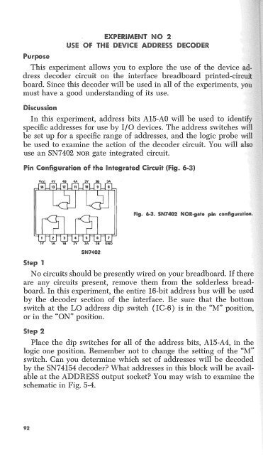
Pin C@nfig11.m1tio!l'll of the Integrated Cireuit {Fig. 6-3)<br />
Step 1<br />
1Y lA 18 2V 2A 28 GND<br />
SN7402<br />
No circuits should be presently wired on your breadboard. If there<br />
are any circuits present, remove them from the solderless breadboard.<br />
In this experiment, the entire 16-bit address bus will be used<br />
by the decoder section of the interface. Be sure that the bottom<br />
switch at the LO address dip switch ( IC-6 ) is in the "M" position,<br />
or in the "ON" position.<br />
Step 2<br />
Place the dip switches for all of the address bits, Al5-A4, in the<br />
logic one position. Remember not to change the setting of the "M"<br />
switch. Can you determine which set of addresses will be decoded<br />
by the SN74154 decoder What addresses in this block will be available<br />
at the ADDRESS output socket You may wish to examine the<br />
schematic in Fig. 5-4.


