


Create successful ePaper yourself
Turn your PDF publications into a flip-book with our unique Google optimized e-Paper software.
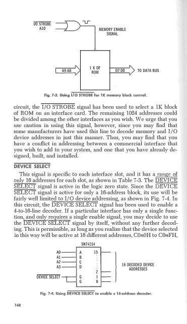
1/0 STROBE<br />
AlO<br />
MEMORY ENABLE<br />
SIGNAL<br />
A9-AO<br />
l K Or<br />
ROM<br />
07-DO<br />
TO DATA BUS<br />
circuit, the I/0 STROBE signal has been used to select a lK block<br />
of ROM on an interface card. The remaining 1024 addresses could<br />
be divided among the other interfaces as you wish. We urge that you<br />
use caution in using this signal, however, since you may find that<br />
some manufacturers have used this line to decode memory and I/0<br />
device addresses in just this manner. Thus, you may find that you<br />
have a conflict in addressing between a commercial interface that<br />
you wish to add to your system, and one that you have already designed,<br />
built, and installed.<br />
DEVICE S!:l!Et'f<br />
This signal is specific to each interface slot, and it has a range of<br />
only 16 addresses for each slot, as shown in Table 7-3. The DEVICE<br />
SELECT signal is active in the logic zero state. Since the DEVICE<br />
SELECT signal is active for only a 16-address block, its use will be<br />
fairly well limited to I/ 0 device addressing, as shown in Fig. 7-4. In<br />
this circuit, the DEVICE SELECT signal has been used to enable a<br />
4-to-16-line decoder. If a particular interface has only a single function,<br />
and only requires a single enable signal, you may decide to use<br />
the DEVICE SELECT signal by itself, without any further decoding.<br />
This is permissible, as long as you realize that the device selected<br />
in this way will be active at 16 different addresses, COnOH to COnFH,<br />
SN74154<br />
AO A 15<br />
Al<br />
B<br />
A2<br />
c<br />
A3<br />
D<br />
2<br />
DEVICE SELECT G l<br />
G 0<br />
1<br />
16 DECODED DEVICE<br />
ADDRESSES


