


Create successful ePaper yourself
Turn your PDF publications into a flip-book with our unique Google optimized e-Paper software.
In the memory address mode, must place the lowest switch at<br />
IC-6 in Lhe "closed" or in the position. This allows the SN7 4154<br />
decoder to be activated only V'!hen there is a match between address<br />
bits Al5-A8 and the bits preset at the HI dip-switch and a match<br />
address bits A7-A4 and the bits preset a1: the LO<br />
addresses between XXXXXXXX XXXXOOOO and XXXXXXXX<br />
are accessible, where X=l or 0. These decoded addresses<br />
present as logic ze:ro pulses at the "ADDRESS" socket ( IC-20) .<br />
nc;u1c'""-''"'' that the first eight addresses in a selected 16-address<br />
are available. Thus, if 10000001 is set for the HI address and<br />
is set for the LO address (bits A 7 -A 4) , addresses 33248 through<br />
would generate logic zero pulses at pins 1 through 8 at the<br />
socket, respectively. Keep in mind that the SN74154<br />
decoder decodes all 16 addresses; you only have access to the "lower"<br />
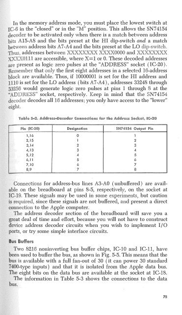
!l'ir. 11c-:m) !Dle$ngnii%knll s74154 0,,11,,,,; p;,.<br />
1,16 ()<br />
2, 15 1 2<br />
2 3<br />
4,13 3 4<br />
5,12 4 5<br />
6,11 5 6<br />
7,10 6 7<br />
8,9 7 8<br />
3,14<br />
:·:'/:. Connections for address-bus lines A3-AO (unbuffered) are avail<br />
"" '"""'v on the breadboard at pins 8-5, respectively, on the socket at<br />
These signals may be used in some experiments, but caution<br />
required, since these signals are not buffered, and present a direct<br />
to the Apple computer.<br />
address decoder section of the breadboard will save you a<br />
deal of time and effort, because you will not have to construct<br />
address decoder circuits when you wish to implement I/ 0<br />
or try some simple interface circuits.<br />
Two 8216 noninverting bus buffer chips, IC-10 and IC-11, have<br />
used to buffer the bus, as shown in Fig. 5-5. This means that the<br />
is available with a foll fan-out of 30 (it can power 30 standard<br />
-type inputs) and that it is isolated from the Apple data bus.<br />
e eight bits on the data bus are available at the socket at IC-18.<br />
The information in Table 5-3 shows the connections to the data<br />
75


