You also want an ePaper? Increase the reach of your titles
YUMPU automatically turns print PDFs into web optimized ePapers that Google loves.
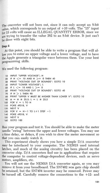
e converter will not burn out, since it can only accept an 8-bit<br />
le, which corresponds to an output of + 10 volts. The "15" input<br />
15 volts will cause an ILLEGAL QUANTITY ERROR, since we<br />
trying to transfer the value 382 to an 8-bit device. It just can't<br />
done with eight bits.<br />
t this point, you should be able to write a program that will alyou<br />
to enter an upper voltage and a lower voltage, and to have<br />
:tite Apple generate a triangular wave between them. Use your best<br />
togramming skills.<br />
e used the following program:<br />
INPUT "UPPER VOLTAGE"; H<br />
IF H = 0 THEN 40<br />
PRINT "VOLTAGE OUT OF BOUNDS": GOTO 10<br />
INPUT "LOWER VOLTAGE"; L<br />
IF L = 0<br />
PRINT "VOLTAGE OUT OF BOUNDS": GOTO 40<br />
IF H > L THEN 90<br />
PRINT "UPPER V MUST BE HIGHER THAN LOWER V": GOTO 10<br />
H = H * 25.5: L = L * 25.5<br />
FOR V = l TO H<br />
POKE 49318, V<br />
NEXT V<br />
FOR V = H - 1 TO L + 1 STEP - 1<br />
POKE 49318, V<br />
NEXT V<br />
GOTO 100<br />
";n your program and test it. You should be able to make the meter<br />
edle "swing" between the upper and lower voltages. You may use<br />
time delay, or delays, if you wish to slow the meter movement so<br />
t<br />
can easily watch it.<br />
experiment clearly shows you how a simple DI A converter<br />
y be interfaced to your computer. The NE5018 used internal<br />
tches, and much of the analog circuitry has been placed on the<br />
nverter chip. D/ A converters find use in applications that require<br />
e computer to control voltage-dependent devices, such as servo<br />
tors, amplifiers, etc.<br />
ou will not use the NE5018 D/ A converter again, so you may<br />
it from your breadboard. The SN7 402 NOR gate chip should<br />
retained, but the SN7 404 inverter may be removed. Power may<br />
turned off. Carefully remove the connections to the + 12- and<br />
131


