


You also want an ePaper? Increase the reach of your titles
YUMPU automatically turns print PDFs into web optimized ePapers that Google loves.
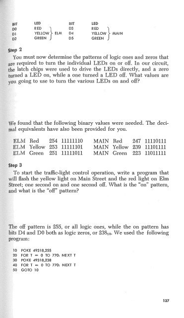
LED<br />
BIT<br />
RED } D3<br />
YELLOW EL M D4<br />
GRE EN D 5<br />
LED<br />
RED }<br />
YELLOW<br />
GRE EN<br />
MAIN<br />
.<br />
You must now determine the patterns of logic ones and zeros that<br />
required to turn the individual LEDs on or off. In our circuit,<br />
latch chips were used to drive the LEDs directly, and a zero<br />
ed a LED on, while a one turned a LED off. What values are<br />
u going to use to turn the various LEDs on and off<br />
e found that the following binary values were needed. The deci<br />
. equivalents have also been provided for you.<br />
Red 254 11111110<br />
Yellow 253 11111101<br />
Green 251 11111011<br />
MAIN Red 247 11110111<br />
MAIN Yellow 239 11101111<br />
MAIN Green 223 11011111<br />
To start the traffic-light control operation, write a program that<br />
'II flash the yellow light on Main Street and the red light on Elm<br />
reet; one second on and one second off. What is the "on" pattern,<br />
d what is the "off' pattern<br />
e off pattern is 255, or all logic ones, while the on pattern has<br />
ts D4 and DO both as logic zeros, or 23810• We used the following<br />
POKE 49318,255<br />
FOR T = 0 TO 770: NEXT T<br />
POKE 49318,238<br />
FOR T = 0 TO 770: NEXT T<br />
GOTO 10<br />
137


