


You also want an ePaper? Increase the reach of your titles
YUMPU automatically turns print PDFs into web optimized ePapers that Google loves.
logic value of the bus is unknown. Whenever a logic zero is app<br />
to one of the bus buffer enable inputs, the selected buffer passes<br />
data onto the bus. The condition in which more than one buffer<br />
been enabled is not allowed, since bus conflicts will arise.<br />
All of the devices that are to be used with the Apple c.;v•uµutF'J<br />
system to transfer information to the CPU must have three-state o<br />
puts. Thus, even memory chips must have three-state outputs,<br />
they in fact do. The computer designer must be sure that the syst<br />
has been designed so that no two input devices are selected at t<br />
same time. If such a multiple selection takes place, improper ope<br />
tion of the computer occurs.<br />
Input ports that may be used to transfer information to the co<br />
puter are readily constructed using standard three-state integrat<br />
circuits. In most cases, eight individual three-state buffers are us<br />
one per bus line. In most cases, too, the enable inputs are all co<br />
nected in parallel, so that all eight buffers transfer their informati<br />
onto the bus simultaneously. In some cases, the common enabling i<br />
put is provided within the chip so that only a single pin on the chi<br />
is required for the control of all eight bits.<br />
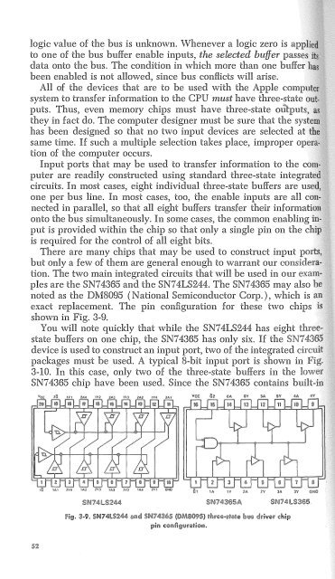
There are many chips that may be used to construct input<br />
but only a few of them are general enough to warrant our cons11ae:ra,<br />
tion. The two main integrated circuits that will be used in our<br />
pies are the SN74365 and the SN74LS244, The SN74365 may also<br />
noted as the DM8095 (National Semiconductor Corp.), which is<br />
exact replacement. The pin configuration for these two chips<br />
shown in Fig. 3-9.<br />
You will note quickly that while the SN74LS244 has eight<br />
state buffers on one chip, the SN74365 has only six. If the<br />
device is used to construct an input port, two of the integrated<br />
packages must be used. A typical 8-bit input port is shown in<br />
3-10. In this case, only two of the three-state buffers in the lower<br />
SN74365 chip have been used. Since the SN74365 contains built-in<br />
SN74lS365<br />
·· :'l-9. !>N74l!i2


