


You also want an ePaper? Increase the reach of your titles
YUMPU automatically turns print PDFs into web optimized ePapers that Google loves.
the logic zero state. In most cases, the dear input will be connected<br />
to +5 volts (logic one) and v.riH not be used.<br />
Each of the integrated circuits may be used to latch and maintain<br />
the data out by the Apple computer during the execution of a<br />
POKE command. It is a simple matter of using an output device<br />
select pulse to activate the latch circuit once it has been properly<br />
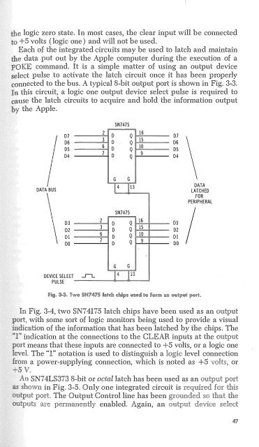
connected to the bus. A typical 8-bit output port is shown in Fig. 3-3.<br />
In this circuit, a logic one output device select pulse is required to<br />
cause i:he latch circuits to acquire and hold the information output<br />
by the Apple.<br />
SN7475<br />
DATA BUS<br />
D7<br />
D6<br />
D5<br />
D4<br />
D3<br />
D2<br />
01<br />
DO<br />
DEVICE SELECT<br />
PULSE<br />
_,,_<br />
2<br />
3<br />
6<br />
7<br />
2<br />
3<br />
6<br />
7<br />
16<br />
D Q<br />
15<br />
0 Q<br />
10<br />
0 Q<br />
9<br />
D Q<br />
G G<br />
l 4 1 13<br />
SN7475<br />
D Q<br />
16<br />
D Q<br />
15<br />
D Q<br />
D Q 9<br />
G G<br />
10<br />
.<br />
D7<br />
D6<br />
D5<br />
04<br />
03<br />
02<br />
DJ<br />
DO<br />
\<br />
DATA<br />
LATCHED<br />
FOR<br />
PERIPHERAL<br />
I<br />
In Fig. 3-4, two SN7 4175 latch chips have been used as an<br />
port, with some sort of logic monitors being used to provide a visual<br />
indication of the information that has been latched by the chipso The<br />
'T' indication at the connections to the CLEAR inputs at the<br />
means that these inputs are connected to +5 volts, or a logic one<br />
The 'T' notation is used to distinguish a level connection<br />
a power-supplying connection, which is noted as +5 or<br />
Vo<br />
An SN7 4LS373 8-bit or octal latch has been used as an<br />
in Fig. 3-5. Only one integrated circuit is<br />
The Output Control line has been<br />
enabledo Again, an


