


Create successful ePaper yourself
Turn your PDF publications into a flip-book with our unique Google optimized e-Paper software.
he six LEDs should be removed from the breadboard, but the<br />
put port should be retained, since you will use it in the next eximent.<br />
Power may be turned off.<br />
rpose<br />
EXPERIMENT NO. 14<br />
LOGIC-DEVICE TESTER<br />
The purpose of this experiment is to show you how the computer<br />
be used to test an electronic device. In this case, simple gates<br />
used.<br />
Most logic chips that contain gates may be tested by applying<br />
own logic levels to their inputs and then comparing the outputs<br />
th the truth-table for the device being tested. In this experiment,<br />
computer will be used in such a manner. One input port and one<br />
tput port are required. Various devices, such as SN7 400, SN7 402,<br />
7 408, etc., may be tested. The test is a functional test, and not<br />
test for dynamic properties, such as switching time, propagation<br />
lay, and other parameters.<br />
You will need to construct an input port and an output port for<br />
e in this experiment. You should be able to construct such ports<br />
'thout further assistance. Many of the previous experiments have<br />
tailed this for you. You may wish to use an SN7 4LS373 chip as<br />
DO<br />
DI<br />
+5<br />
SN7400 QUAD 2-INPUT NANO<br />
ID 3<br />
2 I<br />
:!D<br />
02 6<br />
FROM<br />
DI<br />
03 TO<br />
OUTPUT<br />
INPUT<br />
PORT 04<br />
PORT<br />
05<br />
06<br />
07<br />
I<br />
::ID I,,<br />
,,[DI.<br />
·e=p<br />
DO<br />
02<br />
03<br />
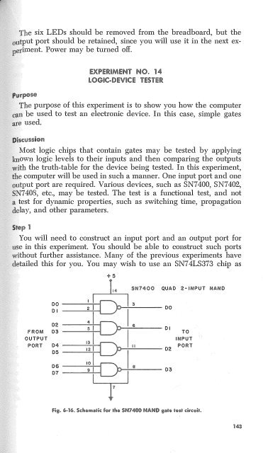
Fig. 6-16. Schematic for the SN7400 NAND gate test circuit.<br />
143


