


Create successful ePaper yourself
Turn your PDF publications into a flip-book with our unique Google optimized e-Paper software.
NSV0_00118<br />
NSV0_00124<br />
NSV0_00119<br />
© Siemens AG 2007<br />
BD2 <strong>System</strong> — <strong>160</strong> ... 1250 A<br />
Introduction<br />
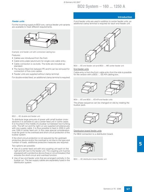
Feeder units<br />
For the incoming supply to BD2 runs, various feeder unit variants<br />
are available to meet different requirements.<br />
If end feeder units are used in addition to center feeder units, an<br />
additional clamp terminal is required for each end feeder unit.<br />
NSV0_00117<br />
Example: end feeder unit with connected cabling box<br />
Features:<br />
• Cables are introduced from the front.<br />
• Cable entry plate (aluminum) for single-core cable entry.<br />
• Cable connection is via bolts. The bolts are included as<br />
standard.<br />
• The factory-fitted link between PE and N can be removed for<br />
connection of five-core cables.<br />
• Feeder units are supplied without clamp terminal.<br />
For double-ended feed, an additional clamp terminal is required.<br />
BD2.-...-EE end feeder unit and BD2.-...-ME center feeder unit<br />
End feeder units<br />
Cable entry is from the front; cable entry from the side is possible<br />
for the version with a BD2.-...-EE-KR cabling box.<br />
NSV0_00120<br />
BD2.-...-EE and BD2.-...-EE-KR end feeder units<br />
The phase sequence can be changed on site by rotating the<br />
busbar pack.<br />
NSV0_00122<br />
BD2.-...-EE double-end feeder unit<br />
To distribute large amounts of power with small busbar crosssections<br />
it is sensible to use a center feed unit in some cases.<br />
It is mounted in the middle of a busbar run between two trunking<br />
units. The left run and the right run are supplied simultaneously<br />
with one supply cable. It is thus possible to feed in 2000 A with<br />
one 1000 A center feed unit. In this case special consideration<br />
must be given to the overload and short-circuit protection of the<br />
busbar system.<br />
If the short-circuit protection is not assured by the upstream<br />
protective device and/or the overload is not due to the type and<br />
number of loads, additional protective measures are required.<br />
Two options are possible:<br />
• Use of a center feed unit with one coupling unit each on the<br />
right and left next to the feeder unit. The coupling unit must be<br />
equipped with a protective device (fuse or circuit-breaker) that<br />
ensures the short-circuit and overload function.<br />
• Use of two end feeder units that are arranged centrally in the<br />
busbar run. The two supply cables are separately fused in the<br />
distribution system.<br />
Distribution board feeder units<br />
For BD2 connection to a distribution board.<br />
N L1 L2 L3 PE<br />
BD2.-...-VE distribution board feeder unit<br />
5<br />
Siemens LV 70 · 2006<br />
5/7


